Diagram symbols for pressure reduction and back pressure regulators. The conceptual difference is mainly in which side the feedback is taken from. A pressure regulator is a valve that controls the pressure of a fluid to a desired value, using negative feedback from the controlled pressure. May 25, 2022 by Robert McGillivray Figure 1: A process and instrumentation diagram The Process and instrumentation diagram, commonly known as a P&ID, shows the connections between process equipment. The diagram indicates the flow directions, safety and control measures, and pressure ratings of a system through visual symbols.

Pressure reducing valve symbol icon Royalty Free Vector
IEC Symbols; JIC / NFPA Symbols; Koyo; DirectLOGIC 05/06 PLC AIO Modules; DirectLOGIC 05/06 PLC AIO Modules - Layout;. Pneumatic Pressure Relief Regulator with Check Valve. Category: Pneumatic Miscellaneous. Stencil: Pneumatic Misc. Tags: pneumatic miscellaneous, pressure relief, regulator, check valve. Piping and Instrument Diagram Standard Symbols Detailed Documentation provides a standard set of shapes & symbols for documenting P&ID and PFD, including standard shapes of instrument, valves, pump, heating exchanges, mixers, crushers, vessels, compressors, filters, motors and connecting shapes. Or Gate Not Gate Correcting Element Diamond In a pneumatic system, the valve is called a regulator. In a hydraulic system, it is called a pressure reducing valve. Notice that the symbols are quite similar, because their function is the same, only with a different medium. In Figure 1, the two symbols are shown side-by-side. P&ID Acronym What does P&ID stand for? The letter meanings are not universal. 'P' could stand for "Piping" or it could stand for "Process". 'I' could represent "Instrumentation" or represent "Instrument". 'D' could mean "Drawing" or it could mean "Diagram".

Symbols for Valves, Pumps and Electrical Equipment on Ship Marine World
1 Scope. This part of ISO 14617 specifies graphical symbols for valves and dampers in diagrams, including symbols for general-purpose valves, those used in fluid power systems and hygienic valves used in the food and pharmaceutical industries. For the fundamental rules of creation and application of graphical symbols in diagrams, see ISO 81714-1. DOWNLOAD THIS CHART An engineer may also include specific details below the control valve symbol. These details may include the size, function, pressure rating, and connection type of the valve. For example, the note 2" 300 RF PB indicates that the P&ID calls for this valve to be a 2" ANSI 300 Raised Face Piston-Balanced valve. The lower symbol indicates a remote pilot operated valves. This valve will still open if the supply pressure increases, via the same dashed line, but will also open due to pressure applied on the remote line X. Note also how the drain line Y can be refereneced to a more stable drain line pressure. Learn more about pressure relief valves Describe the schematic symbol for an external drain. Identify customary locations for the 5 main pressure control valves. Describe a pressure reducing valve using the 5 main characteristics used to classify pressure control valves. Describe the basic operation of a pressure reducing valve.

Pilot operated pressure reducing valve symbol Valve, Pressure, Hydraulic systems
Pressure regulators reduce a supply (or inlet) pressure to a lower outlet pressure and work to maintain this outlet pressure despite fluctuations in the inlet pressure. The reduction of the inlet pressure to a lower outlet pressure is the key characteristic of pressure regulators. When choosing a pressure regulator many factors must be considered. Here are the most common symbols used to identify this type of valves: >> The symbol commonly used to represent a pressure reducing valve in hydraulic systems is as follows: It's a general symbol. >> The hydraulic symbol for a one-way pressure reducing valve: >> Symbol of a differential reducing valve between the pressures of 1 and 2.
Pressure-reducing valve Detailed and simplified forms shown (X2198 and X2199) All formats: CHF 30,00. Add to basket.. ISO 14617-8 — Graphical symbols for diagrams — Part 8: Valves and dampers. Committee : ISO/TC 10/SC 10. ICS : 01.080.30, 23.060.01. Reference No :. A set of standardized P&ID symbols is used by process engineers to draft such diagrams. P&ID symbols exist for all major components and lines, such as valves, vessels, instruments, pumps, compressors, and towers. The ISA S5.1, ISO 10628, and BS 5070 cover the standardization of P&ID symbols and guide process engineers in their plant design.

Pressure Regulator Pid Symbol
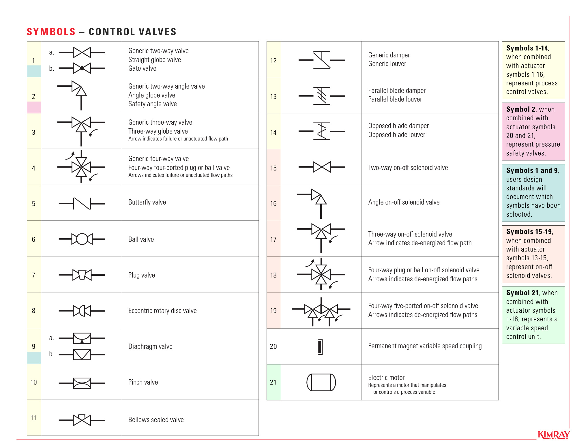
P&ID Symbols for Valves Many types of valves are required in a process plant for flow regulation or on/off purpose. Type of valve employed depends on nature of fluid, flow control required, operating pressure and temperatures as well as surround atmosphere. Here is a list of symbols for various types of valves used in process industry. "a Fig. 2.4 Piping and fittings symbols. (Courtesy MS Visio) Self contained Pressure reducing External regulator tap Back pressure regulator Differential pressure reducing regulator -shown with internal and external pressure taps Self-actuated regulators Self-actuated regulators Relief valves With well Temperature regulator filled system


