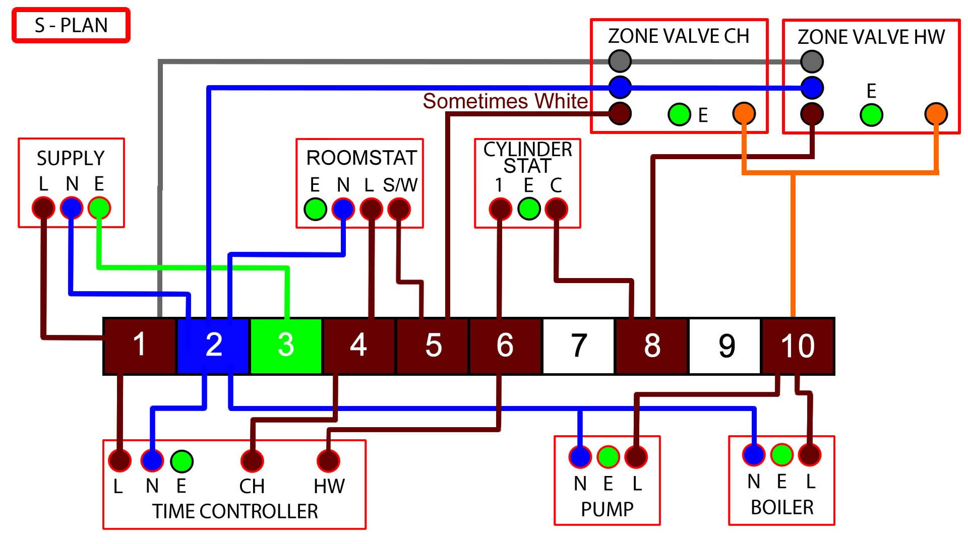
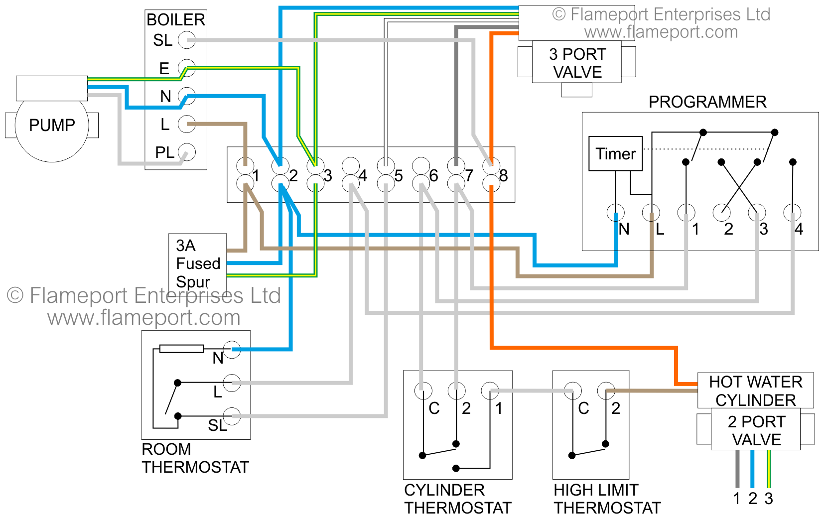
This diagram shows the wiring layout using the most typical components. Here, coloured wires indicate the permanent mains supply to the boiler and programmer. The coloured valve wires are also shown. Other wires are shown in pale grey. S Plan heating systems need to have a nice neat wiring center to enable everything from the plumbing up to work properly! I show you what the wires do and how the system works. The orange.

Underfloor Heating Wiring Diagram S Plan
The schematics show typical S-plan heating systems with under floor heating encorporated. NOTE: An Auto By-Pass valve (ABV) should be incorporated in all systems. NOTE: If a Heat pump manifold has been supplied then there will be no pump on the manifold. UNDERFLOOR HEATING - How To Wire - Wet underfloor heating system. How to wire. Central heating design. In-Floor Radiant HeatBeneath Heat This video is just f. 5 Step Under Floor Heating Installation Simple Underfloor Heating DIY installation guide. A step by step guide to help you fit your system perfectly. Planning an Underfloor Heating Installation Technical information on our underfloor heating systems. Call 0800 232 1501 for more info. Underfloor Heating Next Day Delivery UFH Wiring Diagram SINGLE ZONE - Wired Thermostat Slimline/neoStat 230V AC 50/60Hz 230VAC RT - A2 A1 N L REMOTE PROBE (Optional) TO BOILER 5 16mm Eurocone Screw Connector switch not used LR NEUTRAL neautral earth UFH ZONE VALVE endswitch boiler enable LIVE

S Plan Heating System Wiring Diagram
Can I have a wiring diagram for an S plan central heating system with an UFH wiring centre? - Emmeti Can I have a wiring diagram for an S plan central heating system with an UFH wiring centre? Yes, see schematic below for wiring. - S Plan with EWC-4 V2 The Wiring Diagram Tool below allows you to specify your exact Warmup Thermostat and heating system configuration. Select the Model. Firstly, select the Warmup Thermostat Model you are installing. Diagrams are available for all models from the dial-based MSTAT to the technologically advanced 5iE Wireless Smart Thermostat. Choose the Heat Emitter. Electrical wiring for central heating systems.Part 2 in the series looks at S plan wiring, a system which uses two separate valves. One valve for hot water,. Design Plumbing and Wiring Diagrams Please click on an icon to view the full diagram; Typical Multizone Underfloor on a S-Plan System Typical Single Zone Underfloor on a S-Plan Combi System Typical Single Zone Underfloor on a S-Plan System Multi Zone UFH Wiring Centre S Plan & Combi with Zone Valves Contact Us

Electric Underfloor Heating Wiring Diagram
The current heating is s-plan, the boiler has a pump overrun. The plumber has put in a 2port valve and pump which feeds one zone on the UFH with a remote programmable theromstat. The difficulty I am having is getting the boiler to fire when the UFH calls for heat without sending power to the existing pump (this is from dagrams, its not wired yet). Wireless Touchscreen Programmable Room Thermostat Diagram How to wire underfloor heating thermostat and manifold The answer to this will, of course, depend on the controls you choose for the underfloor heating system. Luckily, all Ambiente thermostats come with full UFH instructions and UFH wiring diagrams, which make installation simple.
The old Honeywell S plan has been around for a long time and can have as many motorised valves as you want, however the whole idea is the micro switch in the valve turns on the boiler, and the thermostat turns the valve on, with the under floor heating the valves don't have any micro switches, so you need the wiring centre which is a relay bank so there is a replacement for the micro switch so. S Plan Wiring Diagram. S Plan wiring diagrams for fully pumped central heating and hot water systems with pump overrun, includes connections for the boiler, hot water and central heating valves, tank stats, central heating wiring centre and room stats. Scroll to the bottom to download the s plan wiring diagram pdf.

Central Heating Wiring Diagram S Plan
S Plan Programmer Connections S Plan central heating & hot water programmer wiring diagram, shown below 몭 rst is the cable (function) followed by the terminal number of the wiring centre. Live (L) = 1 Earth (⏚) = 2 Neutral (N) = 3 CH (on) = 4 HW (on) = 6 S Plan Power Connections S Plan power supply wiring diagram, shown below 몭 rst is the. The two zone valves on a standard S plan have a pair of volt free contacts (orange/grey), these are sued to fire the boiler - greys usually to perm 240v, orange to boiler. When either valve opens, boiler fires. The UFH wiring centre has "boiler fire volt free contacts", these would parallel with the volt free contacts of the orignal zone valves.


