Disconnect the Battery: Always do this before working on any electrical system. This will prevent any accidental shorts or shocks. Identify the Problem: If you haven't already, identify where the problem is occurring. Check if any systems are not working correctly. The 97 Club Car DS wiring diagram helps owners to identify the different parts and connections of their cart. This includes everything from the battery and engine components to the switches and wires that connect the various parts together.

Club Car Ds Electrical Diagram
MANUAL NUMBER 1019285-01 EDITION CODE 0796F0708A https://CartPros.com/f.html https://CartPros.com/f.html This manual covers all 1997 Club CarfiDS Tranquilityfi, V-Glide 36 volt, DS PowerDrivefiSystem 48Ž and DS PowerDrive PlusŽvehicles. The manual is divided into 15 sections. The 1997 Club Car DS 48V Wiring Diagram can be found online. It is important to ensure that you are downloading the correct version, as there are different versions available depending on the model of golf cart that you have. Once you have the correct diagram, you can begin to follow the instructions provided. Club Car DS 1991 - 1997 Gas Wiring Diagram 2 years ago Updated Club Car DS 1991 Gas Club Car DS 1992 Gas Club Car DS 1993 Gas Club Car DS 1994 Gas Club Car DS 1995 Gas Club Car DS 1996 Gas Club Car DS 1997 Gas Club Car DS 1991 Gas Club Car DS 1992 Gas Club Car DS 1993 Gas Club Car DS 1994 Gas Club Car DS 1995 Gas Club Car DS 1996 Gas Club Car DS. In this article, we will discuss the 1997 Club Car DS wiring diagram in detail so that users have all the information they need to properly set up or adjust any wiring or connections related tasks. Understanding Wiring Diagrams
2001 Club Car Parts Diagram Diagram Database
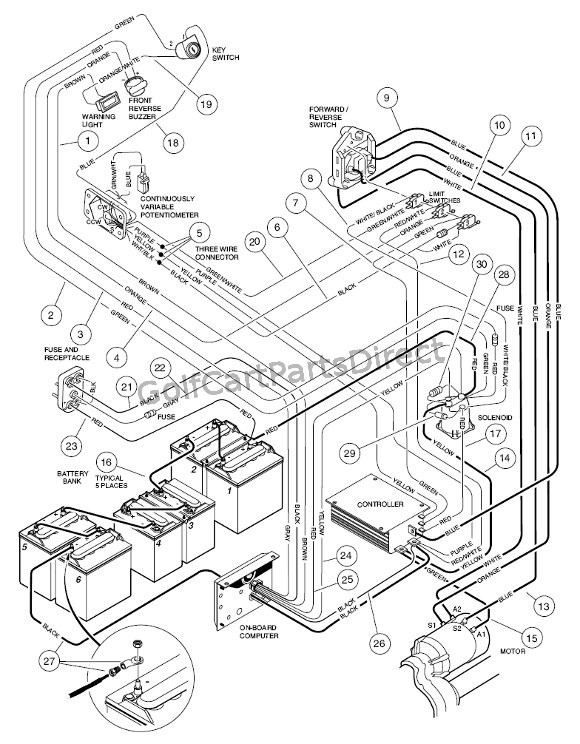
The wiring diagram of the 1997 Club Car DS consists of several components, including the main power source, the battery, the key switch, the solenoid, the motor speed controller, and other components. The 1997 Club Car DS wiring diagram is an invaluable tool for anyone looking to repair or troubleshoot a golf cart. This diagram provides a detailed view of the electrical system of the Club Car, allowing for more efficient repairs and diagnostics. The 1997 Club Car Ds Wiring Diagram is essential for anyone who wants to keep their golf cart up and running. This diagram will provide the wiring information that you need to know in order to make sure your vehicle is operating correctly. wiring schematics . club car . ds. golf cars . rev. e . visio 12/29/10 1 1 85 86 87 30 brake lights relay 1010-clubcar-001 no e. club car sy tem ch a i purple 18 awg r1 orange/ white18 awg golf / street switch i/o ground ped al interlock menu button pot wiper brake switch foward 12v pow er ecntrl

48V Club Car Wiring Diagram 48 Volt Easy Wiring
The 1997 Club Car DS wiring diagram is a schematic that shows the connections between all of the electrical components in the golf cart. The diagram is divided into several sections, each of which corresponds to a different part of the golf cart. The 1997 Club Car DS Wiring Diagram is an essential part of any repair or maintenance project involving a golf cart. This diagrams outlines the wiring connections between the motor and batteries, as well as the switches and lights that are used to control the vehicle. Knowing the exact layout of these components can save time and money in the.
The 1997 Club Car DS Gas Wiring Diagram is an essential tool for owners of the popular golf cart. This diagram is necessary when wiring the vehicle and performing any type of maintenance or repairs. It can help make sure that a job is done right the first time and that the parts are in place and functioning properly. The wiring diagram for a 1997 Club Car DS 48 Volt includes all of the necessary information, including color wiring codes, to make maintenance and repair work easier. It is also helpful if you need to troubleshoot any electrical issues that may arise.

1997 Club Car Ds Wiring Diagram Wiring Draw And Schematic
THE BASIC WIRING IS A Club Car DS Regen I 1999-2002 Wiring WITH THE REVERSE SOLENOID DELETED AND WITH THE AFTER MARKET CONTROLLER THEY USED A CONTROLLER BRIDGE ( small white box with the 12 pin connector)FROM A REGEN II SO HERE IS THE BASIC DIAGRAM The resources section should have a diagram for you. All you need to do is put the wires on just like the old switch. The extra wire may not be needed. J JRJ2 New Member Jan 20, 2021 #3
