Search hundreds of online and print manuals and get the right one from Haynes. Search hundreds of online and print manuals and get expert repair guidance from Haynes. Check Out Top Brands On eBay. Shop For Diagram Electrical Wiring Now. Over 90% Of All Products On eBay Are Brand New. Big Brands, Top Retailers.

Wiring A 220 Switch Diagram
Below is the single phase motor centrifugal switch diagram. The centrifugal switch is used to connect the auxiliary winding with the capacitor and the power source. Once the speed reaches a certain value, the switch will disconnect the capacitor and the auxiliary winding from the power source. This video shows 220V Single Phase Motor Wiring Diagram. A star-delta is used for a cage motor designed to run normally on the delta-connected stator winding. Firstly, the stator winding is. Wiring a single-phase 220-volt motor is straightforward. Step 1 Smaller industrial motors than these are usually single-phase 220-volt. Turn off the power at the breaker that supplies the local blind (blank flat cover) electrical box with the feed that will supply your motor. A 110/220v motor wiring diagram depicts the electrical connections for a motor that can operate on either 110 volts or 220 volts of electrical power. This wiring diagram provides valuable information for electricians and technicians to ensure proper wiring and connection of the motor.

220 Volt Single Phase Motor Wiring
These include: Wire strippers Wire nuts Electrical tape Phillips and flathead screwdrivers Wire cutters Voltage tester Now that we have the necessary safety precautions in mind and the tools at our disposal, let's move on to the step-by-step process of wiring a 220-volt electric motor. Key Takeaways: Single Voltage Motor 208-230V. PO Box 130 350Vaiden drive Hernando, MS 38632-0130 Phone: 662-429-8049 Fax: 662-429-8546 Toll Free: 800-884-0404 www.naemotors.com Dual Voltage Motor with Auto Overload. 115V or 208-230. 2 I am trying to install a single phase 220v electric water pump. I am fairly certain that it is wired correctly however the water pressure it is pumping out is absolutely useless. I have attached how I have wired it: It is a newly refurbished pump, so my first assumption is that I have messed it up. As far as I am aware. Here is a website that explains the operation of different types of electric motors without single-phase electric motor diagrams. My links to wiring diagrams for bathroom fans, ceiling fans, switched outlets, 2-way, 3-way, and 4-way switches, and telephones can be seen here.

Single Phase Motor Wiring
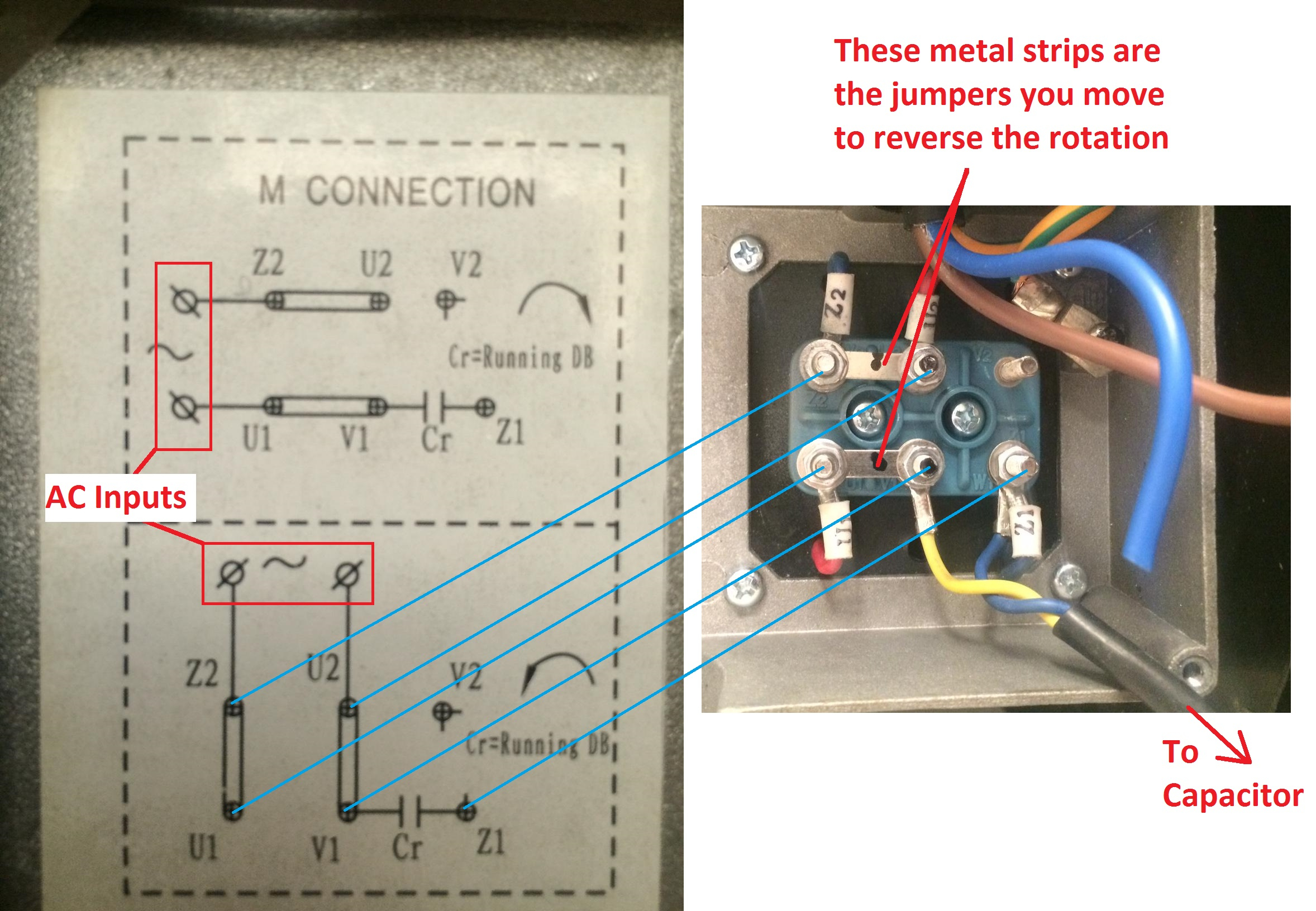
1 1 1 How many motor leads are there? Are they marked or color coded? Does the motor have a rating plate? Can you provide a good picture or otherwise describe what is marked on it. Single phase motors often have information on the inside of the terminal box cover. Jun 6, 2021 at 20:22 For all other SINGLE-PHASE wiring diagrams refer to the manufacturers data on the motor. Diagram DD6 Diagram DD7 M 1~ LN E Diagram DD8 LN E L1 L2 L3 S/C Z1 U2 Z2 U1 Cap. Thermal contacts (TB). Single-phase motors Diag. ER 6 OEDM.. EDM Series A-2 Diags. ER 6, 7 OEN.. EN Series A-3 Diag. ER 6 OFL..ER FlexLine Series E-3/6 Diags. ER 1, 2, 4, 5
Single Phase Motor Wiring | Single Phase Motor Connection with Switch | House Wiring | Complete House Wiring with Inverter Connection | Single Phase Full Hou. In this video, Jamie shows you how to read a wiring diagram and the basics of hooking up an electric air compressor motor. These tips can be used on most ele.

34+ 220V Wiring Diagram Gif Eduram
Step 4. Connect the other end of the wire to its point-of-use, which could be a 220V receptacle or the connection point of an appliance. Remove 6 inches of sheathing and expose the ends of the wires with a wire splicer. Connect the white wire to the silver screw, the ground wire to the green ground nut, and the red and black wires to the brass. Here are the steps for wiring up the motor: Connect the L1 terminal of the motor to the live conductor of the power source. Connect the L2 terminal of the motor to the neutral conductor of the power source. Connect the ground wire of the motor to the grounding terminal of the panel box. Connect the overload switch to the L2 terminal of the motor.


