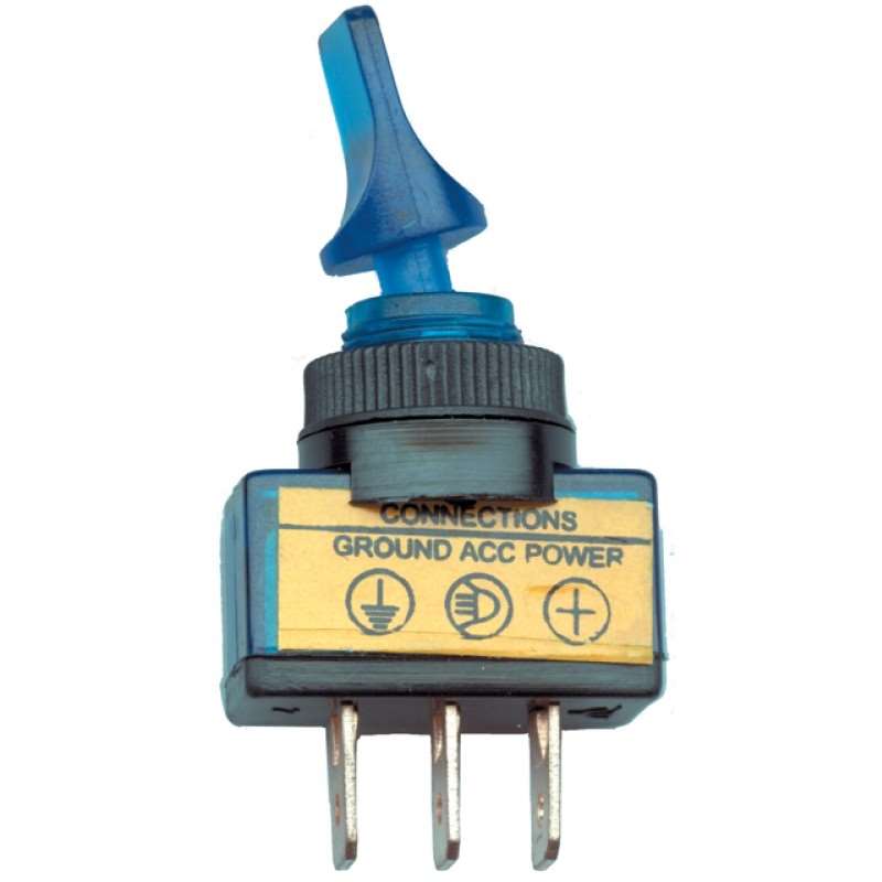
HOW TO WIRE 3 PRONG ROCKER LED SWITCH ImStricken06 28.2K subscribers Subscribe Subscribed 20K Share 2.7M views 8 years ago Supplies In this video: 2 prong switch:. A 3 prong rocker switch is a type of electrical switch that is commonly used to control the power supply to various devices or appliances. These switches are designed to be mounted on a panel or control board, and they feature three prongs or terminals that are used to connect the switch to the circuitry.

Three Pin Switch Wiring Kyla Wiring
1.6K Share 91K views 2 years ago #howto #alwynnicholas LIKE, COMMENT, SUBSCRIBE. How to wire an LED 3 prong 12v Illuminated toggle switch, Applies to all 3 prong rocker switches, non. There are a few steps to properly wiring a 3 prong lighted switch. They are as follows, turning off the power and prepping the cover plate, removing the old cover plate/switchboard, identifying the terminals on the switch, connecting the wires to the switch and troubleshooting. This video shows how to wire an illuminated 3 pin 12-volt DC rocker switch which is usually used in cars, boats, motorcycles and so on. Please pay attention,. Especially if you have never seen one before or are just use to standard toggle switch. a 3 prong toggle switch can cause internal panic with not knowing how to wire a toggle switch.

3 prong male plug wiring diagram
Here is a list of the tools and materials you will need: Rocker switch: Ensure that you have a 3-pin rocker switch that is suitable for your specific application. Wire: Use appropriate gauge wire for your switch and application. Make sure it is long enough to connect the switch to the power source and load. How to wire a 3 prong rocker switch Alwyn Nicholas 1.59K subscribers Subscribe Subscribed 468 Share 61K views 2 years ago #howto #alwynnicholas LIKE, COMMENT, SUBSCRIBE. How to wire an LED. The three prong toggle switch diagram is a visual representation of how the switch works and how it is connected in an electrical circuit. This diagram helps to understand the different components and connections involved in the switch. How to wire a 3 prong rocker switch with light and fitted to an led on my portable fish finder Patreon: https://www.patreon.com/user?u=38543832&fan_landing=true

3 Prong Toggle Switch Wiring Diagram Cadician's Blog
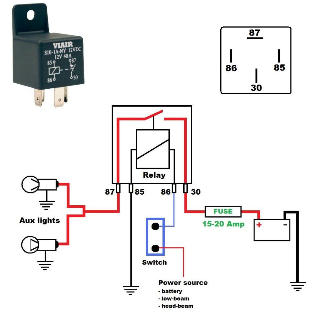
About the 3 Pin Switch One of the most inexpensive means of installing a light bar is the utilization of a 3-pin light bar switch. These round light bar switches have a generic appearance which means they can blend seamlessly with the interior of any ATV, truck, Jeep or boat. The diagram below represents the schematic diagram for a SPST rocker switch: Pin 1 is where the rocker switch receives the input power. Pin 2 is where the accessory that the switch is going to turn on is connected. Pin 3 is where the switch is either connected to ground or left open. Below is a pictorial representation of the schematic diagram:
Rocker switch wiring diagram This is the most basic type of switch - the On/Off rocker switch, (as shown using Oznium's Black Anti Vandal Toggle Switch, mounts in 16mm or 19mm hole). It has just 2 prongs: To add the switch, you'll use one of two wiring a light switch diagrams (shown below), depending on whether the power comes to your light switch first (the most common situation) or to the light fixture first. Either way, follow these five steps for 3-way light switch wiring: Turn off the correct circuit at your electrical panel.

Three Prong Switch Wiring Three Prong Toggle Switch Wiring Brilliant
A 3 G rocker switch is a type of electrical switch used to control an electrical current. The switch works by using three poles, two are connected to the power source while the third is connected to the device or appliance. When the switch is pressed, the current flows through the two poles and the device or appliance turns on. Step 3: Identify the Terminals. Next, identify the three terminals on the momentary switch - Common, Normally Open, and Normally Closed. These will be marked on the switch, but if not, refer to the manufacturer's instructions. Step 4: Connect the Wires. Connect one wire to the Common terminal and the other wire to the Normally Open terminal.


