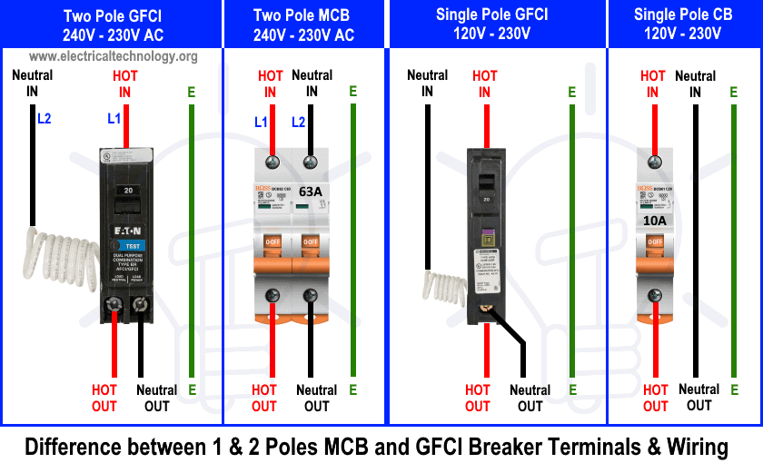
Step 3. Mount the outlet box in your desired location and install a 30 amp outlet in the box. Remove a knockout from outlet box, but drill a hole in the box first if the knockout locations are not suitable for your wiring. Run the wire through the outlet box, and use a cable clamp to secure the wire. This article shows you how to wire a 30-amp single-pole circuit breaker. A 30-amp circuit breaker is usually a double-pole, but it also comes as a single-pole breaker for a 110-volt supply on a 10/2 circuit. The procedure is similar to wiring a regular 15- or 20-amp circuit breaker.

50 Amp Receptacle Wiring Diagram
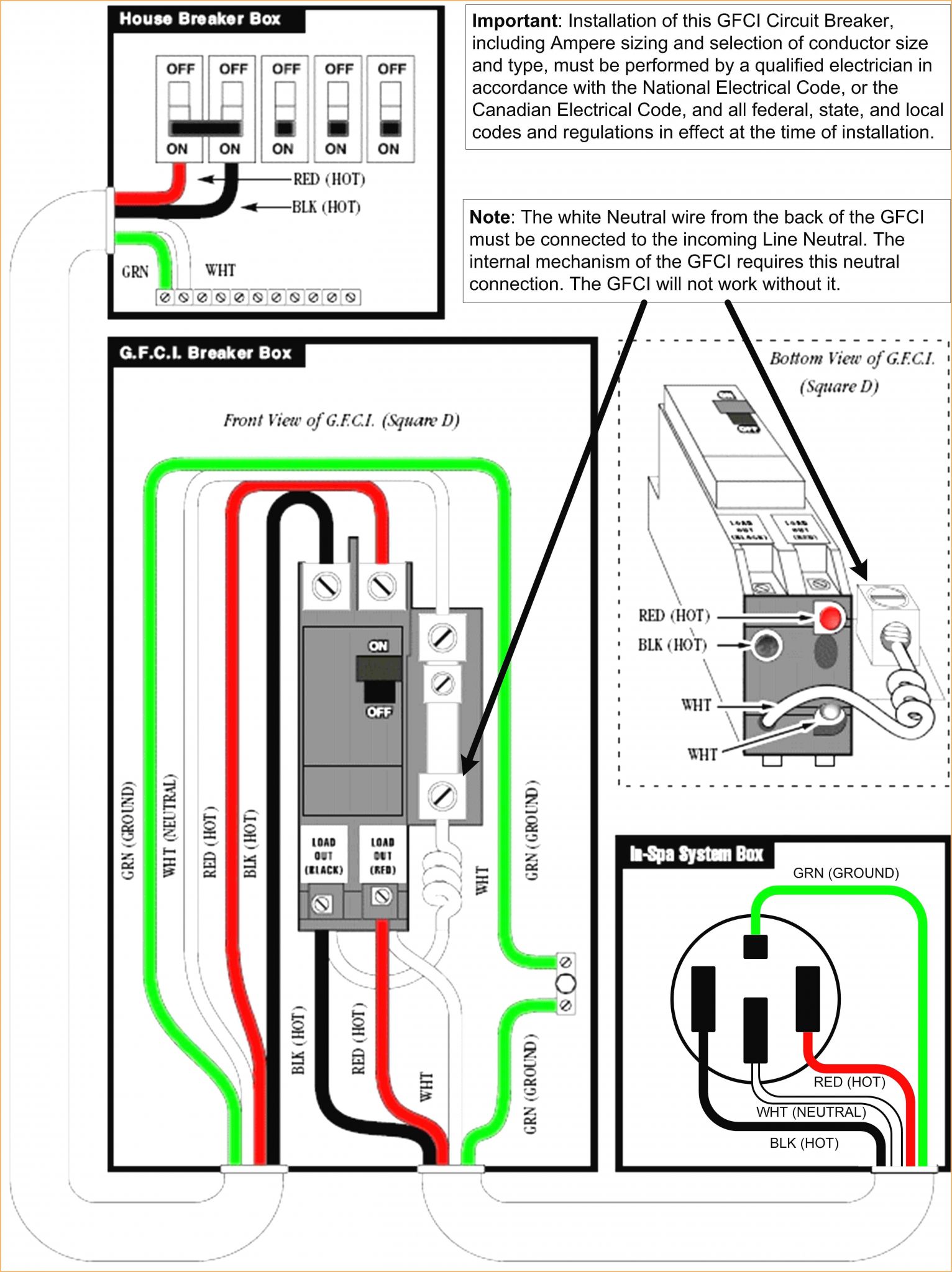
When wiring for a 30 amp breaker, it is vital to use the appropriate wire size and type. The NEC recommends using 10-gauge copper wire for a 30 amp circuit. This wire size can handle the current load without overheating and causing damage. It is essential to choose copper wire as it has better conductivity and is less likely to corrode over time. Wiring Diagram 30 Amp, 240 Volt Circuit Breaker. This is a diagram for a new 30 amp circuit breaker to serve a 30 amp dryer outlet. This is an upgrade of the outdated 30 amp circuit in the previous diagram. This breaker is connected to a 30 amp receptacle with 10/3 cable and a ground wire is included for protection against electrocution not. Installing a Two-Pole Breaker. In residences, two-pole breakers typically control ovens, dryers, ranges, AC condensers, and other big energy users. The photo sequence at right shows a 30-amp, two-pole breaker being installed in a subpanel. As 120v/240v wiring tends to be appliance-specific, this circuit feeds a dryer receptacle. Determine the path the wires will follow and the length of wire needed. Ensure that you have the appropriate gauge wire for a 30 amp circuit. Step 3: Prepare the wires. Strip about 3/4 inch of insulation from the ends of the wires that will be connected to the breaker. Use a wire stripper to make clean and precise cuts.
/double-pole-circuit-breaker-59b9782822fa3a0011a34fde.jpg)
30 Amp Single Pole Circuit Breaker Wiring Diagram Julchens Blog Welt
Green screw - Green or Bare wire (ground) Silver screw - White wire (neutral) Brass screw - Black wire (HOT) Here is the step-by-step wiring process. Step #1. Preparation. You will need a 30-amp outlet receptacle NEMA TT-30R, 10 gauge wires, a weather resistance box, and the wiring tools. Step #2. Safety Tip: All circuit breakers have a safe load capacity rating. For example, a 15-amp circuit breaker has a safe load capacity of 1,440-watts, and a 20-amp circuit has a safe capacity of 1,920-watts. If the total load you want to put on that circuit is greater than 1,920-watts, you must install two separate circuits. Also, make sure the amperage of the breaker matches the amperage of the circuit wires and the appliance being powered. A 20-amp 240-volt circuit calls for 12-gauge wire; a 30-amp circuit calls for 10-gauge wire; a 40-amp circuit calls for 8-gauge wire; and a 50-amp circuit calls for 6-gauge wire. Wiring installation on new construction

afci circuit breaker wiring diagram
A 240-volt circuit needs a three-conductor cable with a minimum wire gauge of 10 AWG. The cable has two hot wires, colored red and black; a neutral wire; and a ground (which isn't considered a conductor). Each hot wire connects to one of the two terminals on the double-pole breaker, the neutral wire gets attached to the neutral bus in the panel, and the ground wire goes on the ground bus. I mostly agree the op will probably need to feed the 30 amp 120v into both lugs and have 15 or 20 amp breakers in this box feeding the receptacles and lighting, I have a horse trailer with a front living space that the 30 amp 120v is plenty I have ( breakers) , it would run a rooftop AC but don't put the coffee maker on the same leg as the AC.
2. Locate the Wiring Diagram. The second step is to locate the wiring diagram for the 30 amp breaker. This can usually be found in the manufacturer's manual or on the box the breaker came in. If you can't find the manual or box, you can also look online for a 30 amp breaker wiring diagram. 3. Connect the Wires. Once you have located the. Steps. Download Article. 1. Switch off the main power switch. This should be located at the top of the breaker panel. 2. Take the cover of the breaker box off. 3. Use an electrical tester by putting the tip of one probe against the ground bus bar and the other against one of the screws of a circuit breaker.

Electrical Load Balance Electric Main Panel Love & Improve Life
This video demonstrates How to wire and properly ground a 30 Amp sub-panel. Perform at your own risk. If not comfortable, do not perform. Making Wire Connections. Inside your 30-amp subpanel, you'll find lugs on the bus bars for each of the incoming wires. The red and black wires go on the hot buses (usually brass), the white wire goes on the chrome neutral bus and the ground wire goes on the ground bus. Inside the main panel, you'll need two adjacent slots in which you can.

/double-pole-circuit-breaker-59b9782822fa3a0011a34fde.jpg)


