Storefronthttps://www.amazon.com/shop/sartingaragehttps://sartingarage.com/See Parts List BelowCheck out Merch Store:https://sartin-small-engine-garage.creat. KOHLER Command PRO EFI 25hp Charging System DiagnosisChapter 4: Test Battery Voltage at Rectifier-RegulatorVideo 4 of 9Contact Your Local KOHLER Dealer for A.
41 Kohler Voltage Regulator Wiring Diagram Diagram For You
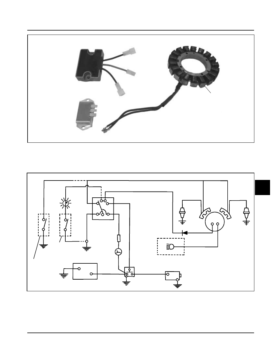
The charging system diagram for a Kohler engine typically includes several key components. These include the stator, voltage regulator, and battery. The stator is a stationary component that generates an AC current as the engine runs.. The charging system relies on a network of wiring and connections to deliver power from the alternator to. Thank you for watching!! If we helped you out and you want to show your support - LIKE, SUBSCRIBE or give us a shout out below. If you saw something you didn. One wire will have varying AC voltage to run a lighting circuit. The other will have a diode in it (what you saw as a resister) to convert AC to DC to feed the battery. Third wire should be going to the coil providing 12v dc to run ignition. The wire with the diode goes to the R terminal on the switch. 1. Part 3 - Identifying Bad Voltage Regulator (Engine ON) In this part, you can test the Kohler voltage regulator. To do that, you need to keep the engine ON. The rectifier regulator takes AC voltage from the stator and converts it to DC voltage. The charging system uses this DC voltage. Step 1 - Place the Probes on the Battery

kohler engine charging system diagram
Method 1: Resistance Test This test is a common method to test the charging system on Kohler engines. But a single resistance test can not give an accurate result. You must do another test with the resistance test. Step 1: Multimeter Setting Take a multimeter and set the multimeter on ohms. It has a Kohler Courage 21 HP single cylinder engine. The charging system uses a stator and a rectifier/regulator. Battery is not being charged. Bought new battery to be safe. Still not charging. Wiring is a 3 wire flat with the 2 outside wires being the AC Voltage coming from stator and middle wire is for battery voltage. With the help of a Kohler Charging System Diagram, you can quickly identify and solve any problems that arise with your engine's charging system, helping you get back on the road faster. Ac712s Charging Problems Talking Tractors Simple. Kohler Ch732 3011 Vermeer 23 5 Hp 17 Kw Parts Diagram For Ignition Charging Group 24 1437 Ch682 752. Ch18. Messages. 9,631. May 4, 2014 / KOHLER ch740 27 hp not charging batteruy. #7. Most likely it isn't killing the spark, it is killing the fuel solenoid on the carb, unless you have the spark advance modules, which require 12v to operate. Kohler voltage regulators require 12v to open the internal switch to charge the battery.

Kohler Starter Generator Wiring Diagram
KOHLER Command PRO EFI 25hp Charging System DiagnosisChapter 7: Rectifier-Regulator Ouput TestVideo 7 of 9Contact Your Local KOHLER Dealer for Assistance: ht. This diagram provides a map of the connections between all the components, outlining how each one interacts with the rest. With the help of this diagram, it's easy to assemble the regulator correctly, ensuring a safe and efficient operation.
Alternator Voltage Regulation 101 (with Wiring Diagrams) - In The Garage with CarParts.com Learn how a car alternator works and find detailed alternator wiring diagrams, including for 3-wire connections in this article. Read on. 1) Charging coils are intended to charge batteries while driving 12DC loads and are available in 1A, 3A and 7A. These are ~ twice the voltage of lighting coils to leave enough voltage after rectification. 2) Lighting coils are intended to power incandescent AC bulbs on vehicles without starters.

kohler voltage regulator wiring diagram Naturalial
The purple wire from the center of the regulator is the charging lead. It should be hooked to a ring terminal on the battery cable that is on the battery side of the solenoid. However.the voltage is rather high it should be 16 to 18 volts DC Max. Higher voltage can overcharge and "cook" the battery. Model: 20--300 kW Market: Subject: Industrial Voltage Regulator Kits 326930, GM24494, GM24495, and GM24496 Use the following procedure to replace an existing voltage regulator with one of the RMS sensing voltage regulators. Refer to the wiring diagram shown in Figure 1. Observe the following safety precautions while installing the kit.
