How does the hydraulic cylinder work? Гидравлика и пневматика 1.7K Likes 2018 Apr 18 How does the hydraulic cylinder work? A hydraulic cylinder has the following parts: piston, rod, seals,. A hydraulic cylinder is a mechanical actuator that gives a unidirectional motion through the force of the hydraulic liquid. It is also referred to as a linear hydraulic motor. It has a wide area of applications, ranging from the construction industry to mechanical machines. Without this, we can not see the enormous development of the nations.

HYDRAULIC SYSTEM FOR BEGINNERS Mechanical Engineering Professionals
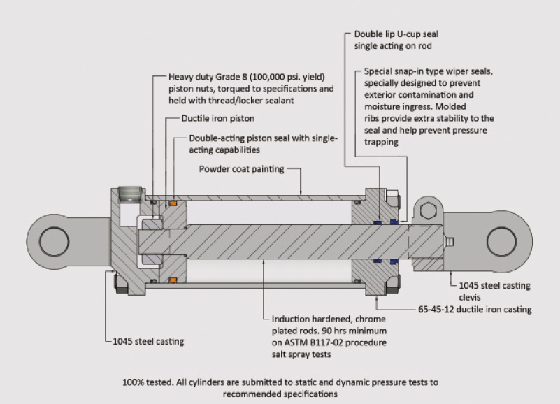
Piston Rod Typically made from cold-rolled steel fortified with hard chrome plating, the piston (cylinder) rod is attached to the cylinder head and the piston. Hard chrome is essential for giving piston rods the ability to last a long time. The piston rod also enhances the seal, which helps prevent leaks. Seal Gland A hydraulic cylinder is the actuator or 'motor' side of the system. The 'generator' side of the hydraulic system is the hydraulic pump which brings in a fixed or regulated flow of oil to the bottom side of the hydraulic cylinder, to move the piston rod upwards. The piston pushes the hydraulic oil in the other chamber back to the reservoir. Simple Hydraulic System Hydraulic Schematic Symbols Accumulator Cylinder Double acting Directional Control Valve (manually operated) Dump Pumps Hydraulic System Components: Gear Pump Hydraulic Pump Symbol Hydraulic System Components : Accumulator Accumulator symbol Hydraulic System Components : Directional Control Valve A hydraulic cylinder has eight basic components; the clevis, gland, port (s), barrel, rod, piston, the end cap, and the seal. When combined, these parts allow the hydraulic cylinder to pressurise fluid that mobilises a piston to generate power for a machine.

How to Rebuild a Hydraulic Cylinder Intella Parts Company, LLC
A hydraulic cylinder schematic diagram provides a visual representation of the different components and fluid flow paths within a hydraulic cylinder system. By studying these diagrams, engineers and technicians can gain valuable insights into the functionality and performance of hydraulic cylinders. The hydraulic cylinders on this excavator operate the machine's linkages. Hydraulic cylinders in a hot press of a particle board machine. A hydraulic cylinder (also called a linear hydraulic motor) is a mechanical actuator that is used to give a unidirectional force through a unidirectional stroke. It has many applications, notably in construction equipment (engineering vehicles. The term cylinder is commonly used to describe a device that gives linear force output and movement. A cylinder may also be referred to as a linear actuator. Cylinders are broken down into two main categories: pneu-matic and hydraulic. Pneumatic cylinders can be operated by several types of gases; however, compressed air is by far the most common. 1.3 Hydraulic Cylinders. Define the term actuator and give examples of a rotational electrical actuator and a linear hydraulic actuator. Draw a pictorial diagram of a double acting hydraulic cylinder. Identify the barrel, piston, rod, cap end plate, rod end plate, rod wiper, cap end port, and rod end port. NOTE: the rod end is often called the.
Hydraulic Cylinders, Cylinder Parts and Hydraulic System Parts Supplier
The function of a cylinder in a fluid power system is to convert energy in the fluid stream into an equivalent amount of mechanical energy. Its power is delivered in a straight-line, push-pull motion. Graphic Symbols: Following diagram illustrates standard ANSI (American National Standards Institute) graphic symbols for use in circuit diagrams. 1. Identifying the line types In a hydraulic schematic, each line type has a unique meaning. In addition, colors can be added to indicate purpose of the line. In the figure below, all of the basic line types are shown. The basic line is a solid line that represents a working pressure hose or tube.
Fτ = P∏ (r12 - r22 ) Where: Fτ is the resultant force. P is the pressure distributed load on the surface. ∏ is pi, approximately equal to 3.14159. r1 is the radius of the piston. r2 is the radius of the piston rod. In hydraulic cylinders, the force can easily be multiplied or divided throughout the system. A simple diagram below helps explain the mechanics of the process -- as fluid enters a chamber more force is applied to push or pull the piston rod in or out of the cylinder and, in turn, pivot, push, or pull the component the cylinder is connected to. Hydraulic cylinders come in two types: single acting and double acting.
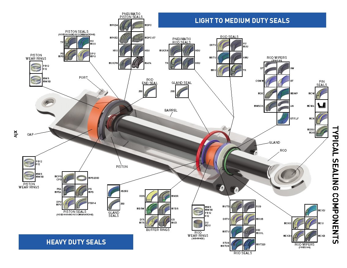
The Function of Seals In a Hydraulic Cylinder หน้าที่ของซีลในกระบอกไฮดรอลิก
Hydraulic Advantages. Hydraulics has many advantages not always found in electrical and mechanical type drives. Hydraulic cylinders and motors can be operated at variable speeds. By varying the volume flowing into the actuator (cylinder or motor) the speed is changed. The hydraulic cylinder or motor can be stalled under a load. Introduction to Fluid Power Forces in Liquids Hydraulic Fluids Pumps Fluid Lines & Fittings Valves Sealing Devices & Materials Measurement & Pressure Control Devices Reservoirs, Strainers, Filters, & Accumulators Actuators Pneumatics Basic Diagrams & Systems Graphic Symbols for Fluid Power Diagrams Basic Diagrams and Systems
