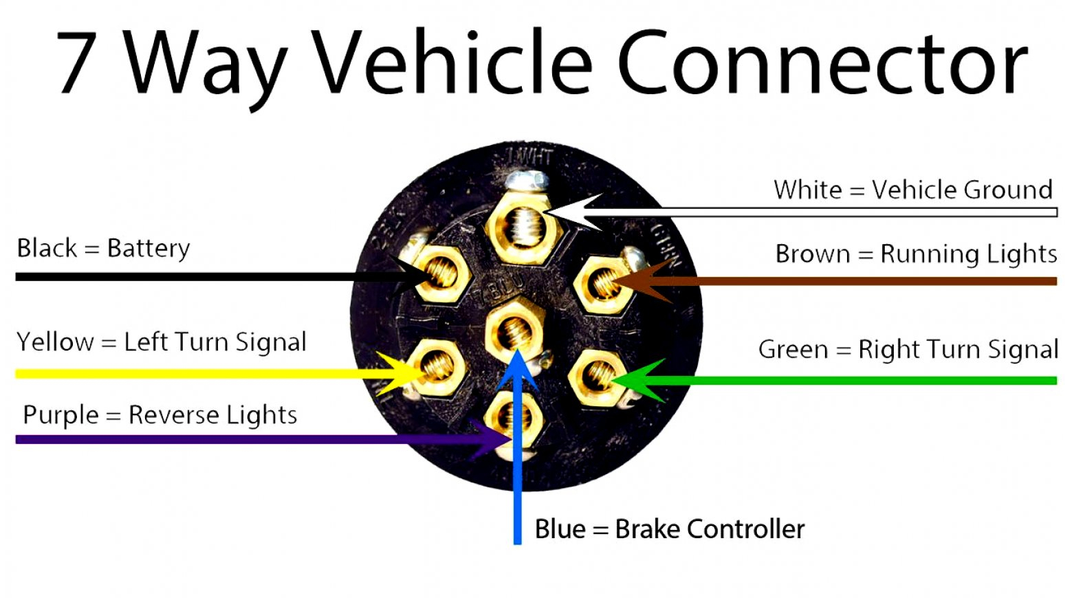
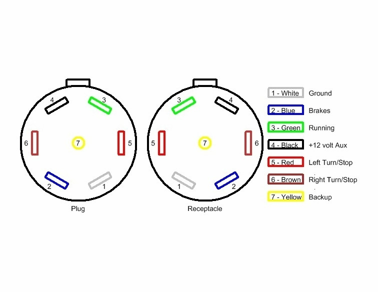
A 7-way plug connects your trailer and tow vehicle and provides the required lights, turn signals, brake power, battery hot lead, reverse lights, and ground. Most of us aren't electricians, but that doesn't mean wiring a trailer or replacing corroded wiring is beyond us. We'll walk you through the wiring process--it's easier than you think! This trailer wiring guide comes complete with a color coded trailer wiring diagram for each plug type, including a 7 pin trailer wiring diagram, this guide walks through various trailer wiring installation solution, including custom wiring, splice-in wiring and replacement wiring. If your vehicle is not equipped with a working trailer wiring harness, there are a number of different solutions.

Trailer Lights Wiring Diagram South Africa Circuit Diagram
Trailer Wiring Connectors. Various connectors are available from four to seven pins that allow for the transfer of power for the lighting as well as auxiliary functions such as an electric trailer brake controller, backup lights, or a 12V power supply for a winch or interior trailer lights. Choose a connector that has the required number of. The 7-pin trailer plug is the most common type used for connecting trailers to vehicles, providing all the necessary signals for lights, brakes, and other electrical components. In this comprehensive guide, we will walk you through the complete wiring diagram for a 7-pin trailer plug, making installation a breeze. The 7-Way Trailer Plug is around 2″ diameter connector that allows an additional pin for an auxiliary 12-volt power or backup lights. It is usually used for towing heavy-duty cargo trailers, aluminum trailers, dump trailers, utility / landscape trailers, equipment trailers, open car haulers and enclosed car haulers. Check out our Trailer Wiring Diagrams. Wiring Guide for Trailer Plugs, Adapters & Sockets. Wiring Guide for Trailer Plugs, Adapters & Sockets . Featured Products. 6" Drop Hitch (SSBM) Fits 2" Receiver $ 240.00; 2.717" Grease Caps - Fits Most 7,000 lb Axles $ 13.95; 2.44" Grease.

Rv Trailer Plug Wiring Diagram Non Commercial Truck, Fifth in 7 Wire
Step 3: Test Connections. Before sealing everything, conduct a thorough test. Connect the trailer plug to the vehicle's socket and check if all lights and functions are working correctly. Test the tail lights, turn signals, brake lights, and any other accessories connected to the plug. If you have a 4-way plug, add a 5-way with a 4-to-5-way adapter Use a circuit tester to confirm wire function. Step 2: Connect Ground to Vehicle Frame Just like we did on the trailer, we now have to connect the ground on the vehicle side. Attach the white ground wire to a clean, bare metal surface on the vehicle frame. The trailer plug wiring diagram serves as a guide to help you properly connect your trailer's electrical system to your vehicle's system. There are several different types of trailer plugs, but the most common is the 7-pin round plug. This plug is typically used for heavy-duty trailers and provides connections for the ground, tail lights. 7 Way Plug Wiring Diagram Standard Wiring* Post Purpose Wire Color TM Park Light Green (+) Battery Feed Black. S Trailer Electric Brakes Blue GD Ground White A Accessory Yellow This is the most common (Standard) wiring scheme for RV Plugs and the one used by major auto manufacturers today. * Always test wires for function and wire.

Rv Trailer Plug Wiring Wiring Diagrams Hubs Trailer Wiring Diagram
There are two key components that make up these systems: The 7-pin connectors and wiring mounted on both the vehicle and trailer. The connecting wires that join to circuits to carry signals and power. There are two common configurations of 7-way connectors: Standard: The most widely used. Reverse Pin-Out: A configuration with opposing pin. Identify the wires: The first step is to identify the wires coming out of your trailer plug. There are typically six wires in a 6 wire trailer plug: ground, brake, tail lights, left turn, right turn, and reverse lights. Use a wire stripper to remove about 1/2 inch of insulation from the ends of each wire. Connect the ground wire: The ground.
How to wire a trailer plug - 7 pin (diagrams shown) Trailer Wire Color Codes - Colors Coordinate With Trailer Wiring Diagram; Connector Style Pin Function Color Description; 7-Pin: 6-Pin: 5-Pin: 4-Pin: 1: Ground: White: Ground for all trailer electrical functions. 2: Tail Lamps Running Lights Side Markers: Brown: Power for all normally ON lamps. Tail, Running & Side marker lights. 3:

7 Way Trailer Plug Wiring Diagram Wiring Diagram
6 Pole Round Connector TM 000 Truck Plug TM 000 Trailer Plug TM- Tail Light (Brown) ST-Brake (Black) GD- Ground (White) LT-Left Turn (Yellow) RT- Right Turn (Green) A- Auxillary Hot Wire (Red) Note: Locate wires by function only. Color coding is not standard among all manufacturers. 7 Pole Round Connector Vehicle End o Trailer End The below diagrams are for 12 pin flat & 7 pin flat trailer plug wiring and socket wiring. Below are standard NZ trailer wiring colours. 7 pole Amp rating per pole 15A at 12V. 5 pole Amp rating per pole 35A at 12V (12 Pin top row)


