Save Time & Money On The Exact Dodge Haynes Manual You Need For Your Project. eManual Online Provides Descriptive Manuals with Diagrams & Pictures for Your DIY Project 170+ Stores Nationwide - Click & Collect Within 30 Minutes! Find The Part You Need With Our Car Registration Look Up Tool! Browse Our Extensive Range.

Dodge Truck Alternator Wiring
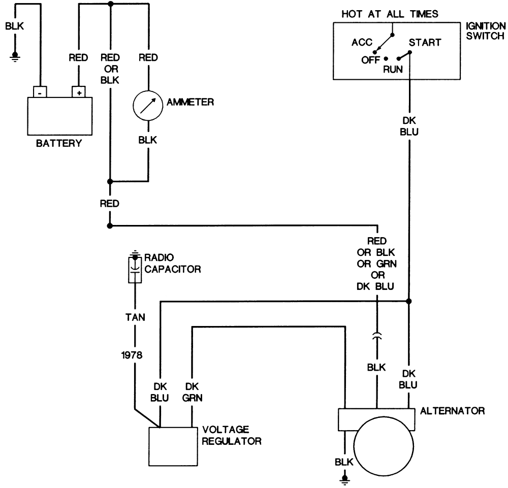
How to wire up a external voltage regulator for an alternator.Amazon Affiliate LinksAdjustable Dodge Voltage Regulator: https://amzn.to/2ROOiJeOEM Dodge Volt. Mopar Charging Systems. Diagram #1 shows the basics of the early alternator / voltage regulator (VR) design. There are 2 brushes in the alternator, each one has a field terminal, one is labeled "FLD", the other is labeled "GND". The GND brush is grounded with the brush mounting screw. the other brush is the (+) brush (or field) and attached to. The Dodge Alternator Wiring Diagram is an invaluable tool for any automotive enthusiast or professional. By studying this diagram in depth, you can gain a better understanding of your car's electrical system, truly becoming a master of automotive electrical wiring. With practice, you can become an expert in car repairs and maintenance - all. Such intricate wiring designs demonstrate the value of having a three- or four-wire alternator in your system. That's all there is to it! With this diagram, you should easily wire up your alternator and trigger the ignition switch. If you have any questions, be sure to consult a professional mechanic. What Are The 4 Wires On An Alternator

Dodge Alternator Wiring Diagram Collection
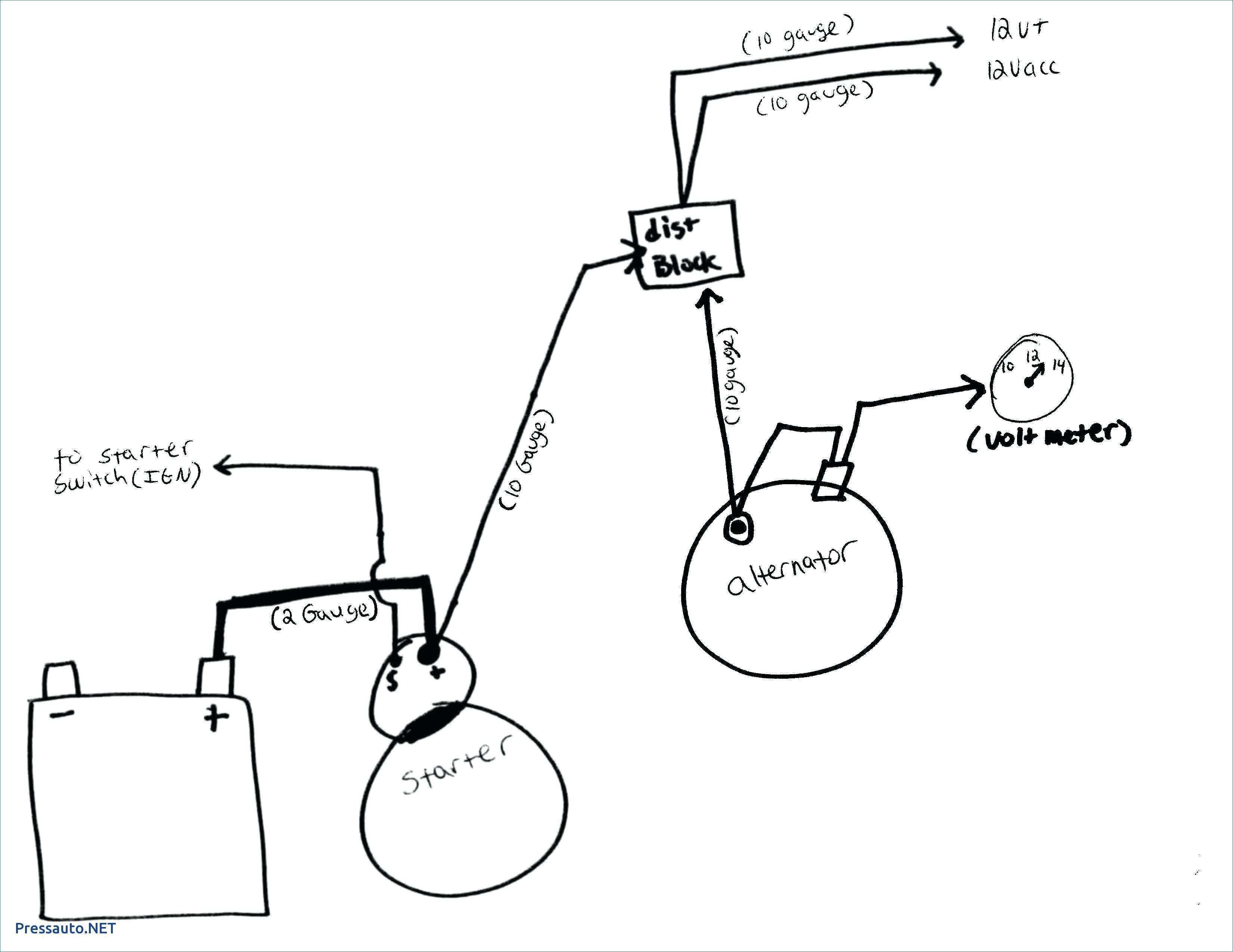
This is a three-wire alternating wiring diagram showing the connections between the different components of a circuit. The circuit comprises three main wires: battery positive cable, voltage sensing wire, and ignition wire. The ignition input wire is attached to the engine. It conducts electricity from the engine to the alternator while the. 537 posts · Joined 2008. #3 · Jan 30, 2009. To identify the (+) field circuit and (-) field circuit terminals on the alternator, look at the back of the alternator and put the "BATT" terminal at the 12 o'clock position. The two "FLD" terminals would appear as though they were at approximately the 10 o'clock and 11 o'clock positions. Simplified Charging Diagram w/Dual Field Alternator & Electronic Voltage Regulator Simplified Electronic Ignition System Diagrams (4-Pin & 5 -Pin). MyMopar.com is pleased to offer FREE wiring diagrams for all Mopar cars from 1955 thru 1975 and some various trucks. Beginners Guide to Automotive Wiring Learn how to install a signal wire on your diesel alternator. Here we'll do just that on with a Dodge Gen 1 and 2 Cummins alternator. Find your digital tac.

Dodge Cummins Alternator Wiring Diagram
Step 3: Connect the Output Wire. Locate the output wire on the new Dodge 1 wire alternator. This wire is responsible for charging the battery and providing power to the vehicle. Connect this wire to the positive terminal of the battery. Ensure that the connection is tight and secure. A typical 3-wire alternator wiring diagram with an internal voltage regulator. Computer-Controlled Voltage Regulation Many late-model vehicles use the engine computer, which is often referred to as the powertrain control module (PCM), to control alternator output.
Step #1 Disconnect the battery! Always do this step! Step #2 Locate the voltage regulator, usually on the firewall. Remove the ARM and FLD wires and tape them back with electrical tape in case you or the next guy want to re-install a generator. These wires connect to the generator and you don't need them. Step #3 Remove the 2 wires from the. Unlock the mysteries of your Dodge alternator wiring diagram as we take you on a technical adventure. Step into the realm of wires and currents, where creativity meets functionality. Unveil the intricate web of connections, igniting your curiosity and unraveling the secrets behind your vehicle's power production. From the mesmerizing dance of electrons to the harmonious symphony of circuits.

Wire Alternator Wiring Diagram Dodge Oxygen Sensor Diagram
The Bosch is roughly 1.5 times bigger and uses totally different brackets. The 2 field wires from the alternator both run to the voltage regulator, IIRC. The big wires runs to the firewall plug, and on inside to the amp gauge I believe. Rob M. '93 D150 RC SWB, 5.2 Magnum, NV4500 5-spd, 9.25" diff. '72 D100 RC LWB, PT project. Chrysler-Plymouth-Dodge Electrical Diagrams. Click here for more help with electrical issues and alternator upgrades. Dave Wordinger wrote: This is an engine compartment wiring diagram for a 1969 Valiant. B bodies had a horn relay rather than the horn button activating the horn directly. Other than that, they were very similar.


