Electrical symbols & electronic circuit symbols of schematic diagram - resistor, capacitor, inductor, relay, switch, wire, ground, diode, LED, transistor, power supply, antenna, lamp, logic gates,. A solenoid ( / ˈsoʊlənɔɪd / [1]) is a type of electromagnet formed by a helical coil of wire whose length is substantially greater than its diameter, [2] which generates a controlled magnetic field. The coil can produce a uniform magnetic field in a volume of space when an electric current is passed through it.

Relays Symbols. Coil, Solenoid, & Contacts Symbols
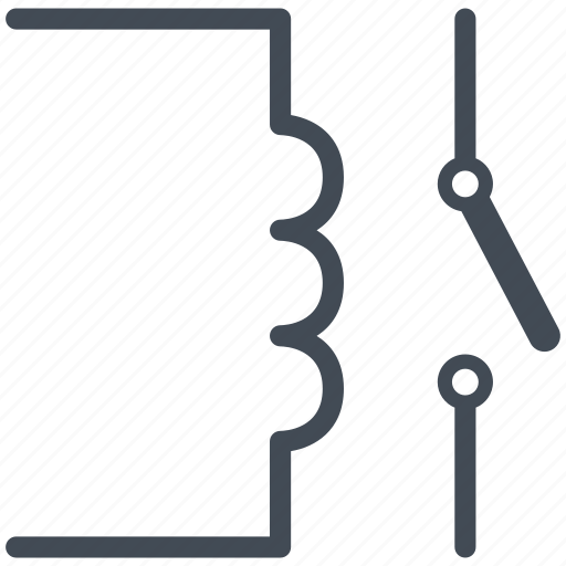
Relays Symbols - Coil, Solenoid, Electromagnet & Contacts Symbols Solenoid operated Relay The solenoid operated relay has a coil wound around a core that produces magnetic field when the coil is energised by the current flowing through it. The magnetic field pulls the lever (movable contact) to either make or break the contact. Solenoid Symbol in Electrical Schematic. In electrical schematics, a solenoid is represented by a specific symbol that indicates its function and operation. The solenoid symbol is commonly used to represent a device that converts electrical energy into linear motion. It is widely used in various applications, including control systems. 1. Solenoid valve symbols in fluid power diagrams Fluid power drawings are crafted up by engineers to understand and analyze power units. These diagrams have standard-based graphic symbols representing the complete operation and direction of fluid flow within a power unit. Figure 2: A 2/2 valve symbol Basic electrical and electronic graphical symbols called Schematic Symbols are commonly used within circuit diagrams, schematics and computer aided drawing packages to identify the position of individual components and elements within a circuit.

Solenoid Wiring Diagram Symbol Easy Wiring
A solenoid is an electrical device that converts electrical energy into linear motion by using a magnetic field. It consists of a coil of wire wound around a magnetic core, with a plunger or armature that can move in and out. The solenoid schematic symbol is commonly used in circuit diagrams to represent a solenoid and its associated components. 20 - Elect. operated valve (solenoid valve) 21 - Distance Relay 23 - Temperature Control Device 24 - Volts per Hertz Relay 25 - Synchronizing or Synchronism-Check Device 26 - Apparatus Thermal Device 27 - Undervoltage Relay 29 - Isolating Contactor 30 - Annunciator Relay 32 - Directional Power Relay 36 - Polarity or Polarizing Voltage Devices The symbol for the solenoid or the pressure-operated valve has the same number of squares as the valve has positions. The right-hand square shows the valve in its non-actuated (rest) position, the left-hand square corresponds to a valve in its actuated (work) position. 2 positions 3 positions Function: NC = normally closed (rest position) A "solenoid" is nothing more than a coil of wire designed to produce a magnetic field when energized. Solenoid actuators work by attracting a movable ferrous armature into the center of the solenoid coil when energized, the force of this attraction working to actuate a small valve mechanism.
Circuit, diagram, electric, electronic, solenoid operated relay icon
A solenoid is an electrical device that converts electrical energy into a linear mechanical force. Electric Motor Controls, G. Rockis, 2001 Electric Motor Controls, G. Rockis, 2001 Contactors Contactor - a control device that uses a small control current to energize or de-energize the load connected to it. Electric solenoids that change valve position by directly moving the valve element are called direct solenoid. Electric solenoids that open small pilot valves and allowing pressurized air to move the valve element are called solenoid controlled pilot operators. Valve Actuator Symbols Spring Push Button Plunger Lever Cam Roller Air Pilot Solenoid
Electromagnet Solenoid A solenoid is a cylindrical coil made of a conductor which produces magnetic field when electricity passes through it. It is also known as Electromagnet. sinθ = y y2 +R2− −−−−−√. (12.7.3) Figure 12.7.1: (a) A solenoid is a long wire wound in the shape of a helix. (b) The magnetic field at the point P on the axis of the solenoid is the net field due to all of the current loops. Taking the differential of both sides of this equation, we obtain.

Circuit, diagram, electric, electric valve, electronic, relay, solenoid
The first operator is the symbol for a solenoid coil that magnetically pushes on the armature pin, which makes sense as the diagonal line leans towards the valve body. Relay Symbols and Electromagnets. The relay are switching electrical devices activated by signals. Most of the time, a small voltage or current is used to switch other voltages or higher currents that may be electromechanical or fully electronic type. The electromagnetic controls are activated thanks to electromagnetic fields generated by.
