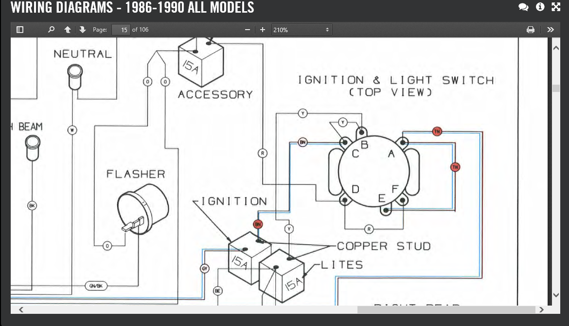
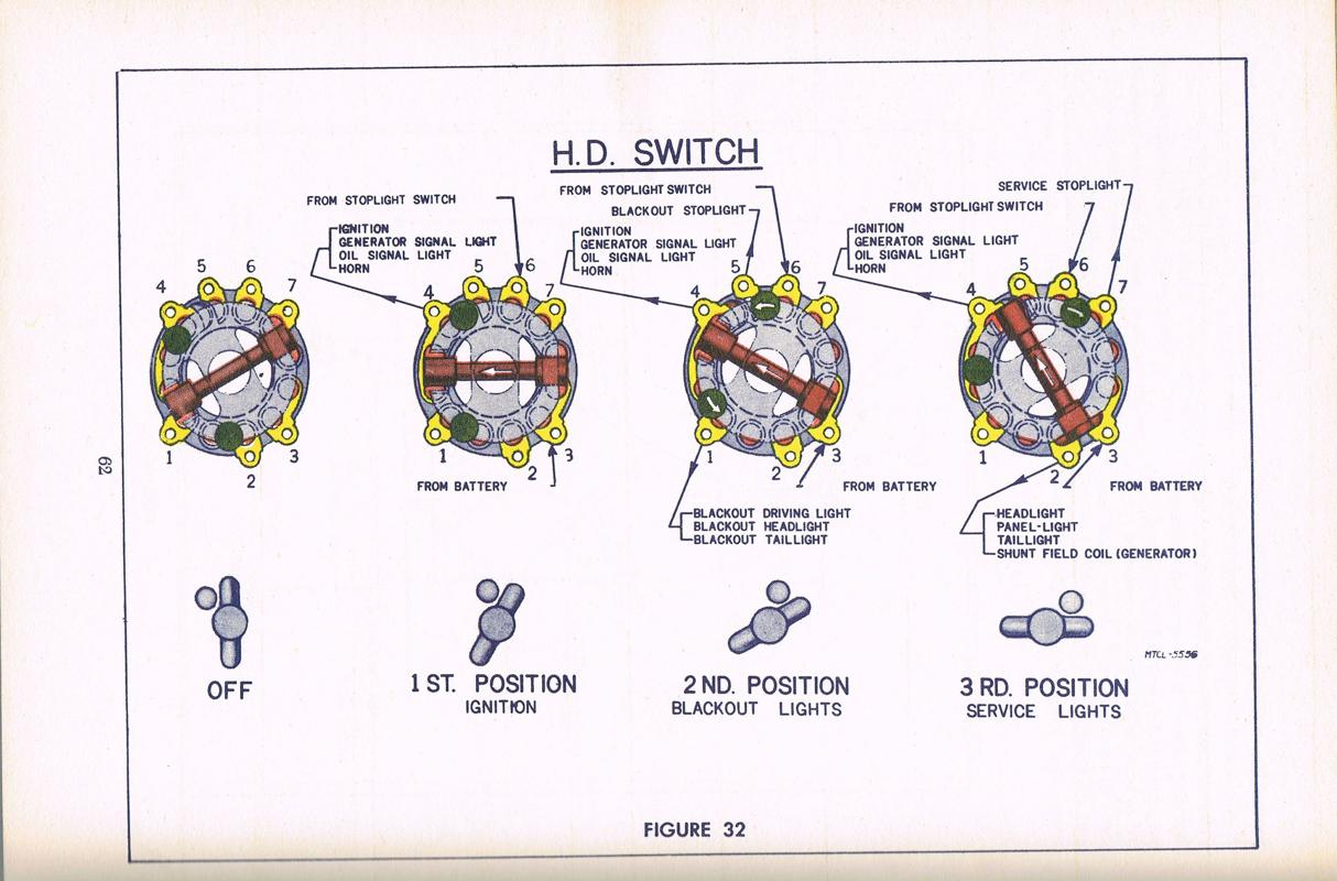
A: A Harley 6 pole ignition switch wiring diagram is a visual representation of the electrical connections and wiring configuration for the ignition switch found on Harley-Davidson motorcycles. It outlines the specific arrangement of wires and terminals required for proper functioning of the ignition system. Learn how to read and interpret a Harley ignition switch wiring diagram to troubleshoot and repair your motorcycle's electrical system. Understand the different components and connections involved in the ignition switch wiring, and get insights on common issues and solutions. Explore step-by-step instructions and diagrams for smooth troubleshooting and successful repairs.

Simple Wiring Harness For Motorcycle
Overview of the Ignition Switch Wiring Diagram. The Harley Davidson ignition switch wiring diagram is a simplified version of the electrical system of your bike. It shows the various components and how they are wired together. The diagram will also help you to identify any electrical connections that you may need to make. The ignition switch allows the rider to start and stop the engine, as well as control various electrical functions of the motorcycle. In this article, we will take a closer look at the Harley 6 pole ignition switch wiring diagram. The 6 pole ignition switch is commonly used in Harley Davidson motorcycles. The diagrams either show entire systems or specific circuits. The circuit specific diagrams only show the components and wiring in the system(s)listed in the diagram title. Always refer to the diagram title for diagram type. Harley ignition switch wiring diagram (specific to your model) 2. Disconnect the battery: Before you begin any wiring work, it is essential to disconnect the negative terminal of your battery to prevent any accidental electrical shorts or sparks. 3. Remove the old ignition switch:

[DIAGRAM] 3 Pole Harley Ignition Switch Wiring Diagram
2003 all flt domestic and international models, ignition switch, lights, sheet 2 of 8; 2003 all flt domestic and international models, ignition harness, sheet 3 of 8; 2003 all flt domestic and international models, hand controls, speedo., tach., & indicators, sheet 4 of 8; 2003 flhtpi models, interconnect harness, sheet 5 of 8 The diagrams either show entire systems or specific circuits. The circuit specific diagrams only show the components and wiring in the system(s)listed in the diagram title. Always refer to the diagram title for diagram type. cover; wiring diagram book contents, 1986 - 1990; 1986 - 1990 xlh all models; late 1985 & 1986 fxwg, fxst/c; 1986 1/2 flst; 1987 & 1988 fxst/c, fxsts; 1987 - 1988 flstc 5 The diagrams either show entire systems or specific circuits.The circuit specific diagrams only show the components and wiring in the system(s) listed in the diagram title. Always refer to the diagram title for diagram type. Troubleshooting Once a problem has been isolated to a specific system or circuit, the circuit specific diagrams will.

6 Terminal Ignition Switch Wiring Diagram
Using a wire cutter, cut off wires of new ignition switch approximately 3 in. (76.2 mm) from switch body. Cut off ring terminals from ends of original wiring harness wires, leaving sufficient harness length to splice wiring and properly mount new switch. 2. See Figure 7. Strip 3/8 in. (9.5 mm) of insulation off both wires to be spliced. The Harley 6 pole ignition switch wiring diagram is a helpful tool for understanding how the switch is connected to the motorcycle. By referring to the diagram, you can be sure your wiring is up-to-date and correct. This will help ensure your motorcycle is getting the power it needs to keep running strong.
2006 all efi softail dom. and int. models, ignition circuit; 2006 all efi softail dom. and int. models, lighting circuit: sheet 1 of 2; 2006 all efi softail dom. and int. models, lighting circuit: sheet 2 of 2; 2006 all efi softail dom. and int. models, horn & instruments; 2006 all efi softail dom. and int. models, starting circuit 5 post ignition switch Diagram. Started by Ironheadmike, July 17, 2018, 07:46:21 AM.. Over on the Shovelhead page at the top is wiring diagrams for a lot of years of bikes. Ironheadmike. Full Member. With what Evo has offered and the original diagram, should be able to make your 5 pole function. User actions. Print. Go Up Pages 1.

Harley 6 Pole Ignition Switch Wiring Diagram Explained Moo Wiring
I recently installed a new ignition switch and rewired the entire bike to the Harley Davidson service manual specs. Both the old and new ignition switches have 6 tabs for attaching wires( sketch shown on left of image) . The service manual wiring diagram shows only 5 tabs on the ignition switch labeled 1-5(sketch shown on right of image). When the ignition switch is turned on, a small electric current is sent through the starter solenoid.. Wiring Diagram. After you have gathered all your materials for the electrical system, it is time to draw or find the wiring diagram suitable for your motorcycle.. Wiring your Harley will take time and effort. This will probably make you.


