Video pixel rate: 25 MHz to 165 MHz (Type A) or to 330 MHz (Type B). Video formats with rates below 25 MHz (e.g. 13.5 MHz for 480i/NTSC) transmitted using a pixel-repetition scheme. Up to 24 bits per pixel can be transferred, regardless of rate. Supports 1080p60. Let's see the pinout diagrams and connections of the most significant HDMI connector types. Table Of Contents HDMI Pinout Type A HDMI connector Pinout Type C (Mini) HDMI connector Pinout Type D (Micro) HDMI connector Pinout Type B HDMI connector Pinout Pin description of HDMI connector HDMI Pinout

Wiring Diagram Micro Usb
HDMI Pinout Explained Generally, pins 1-12 carry the TMDS data transmission. It includes video, audio, and auxiliary data information. They form four separate channels for video data, clock data. These data are organized into three categories. They are the Video data period, Data island period, and Control period. Articles HDMI® Connector Pinout Explained HDMI® Connector Pinout Explained By: CableOrganizer® From streaming, HDTVs and high-end gaming systems to HD DVD and Blu-ray Disc™ players, the connection of choice for today's high-definition electronics is clear: the HDMI® Cable. HDMI pinouts are diagrams that show the connections between different HDMI components. They are used to help understand the layout of an HDMI connection. The diagrams are typically arranged in rows and columns, with each connector labeled for its specific purpose. High-Definition Multimedia Interface ( HDMI) is a proprietary audio/video interface for transmitting uncompressed video data and compressed or uncompressed digital audio data from an HDMI-compliant source device, such as a display controller, to a compatible computer monitor, video projector, digital television, or digital audio device. [3]

Question HDMI Pinout BitBuilt Giving Life to Old Consoles
Other resolutions: 320 × 127 pixels | 640 × 253 pixels | 1,024 × 405 pixels | 1,280 × 507 pixels | 2,560 × 1,013 pixels | 2,206 × 873 pixels. Original file (SVG file, nominally 2,206 × 873 pixels, file size: 2 KB) File information Structured data Captions English Add a one-line explanation of what this file represents Summary [ edit] If you've shopped for an HDTV, a PlayStation 3, or an HD-DVD or Blu-ray player, you've probably heard about HDMI. It can seem like just one of many connections on televisions or home-theater receivers. But HDMI is more than a port on the back of a TV (and the often expensive cable that fits inside). It's a set of rules for allowing high-definition electronic devices to communicate. An HDMI pinout diagram provides information regarding the input and output connections of each device. The diagram outlines each pin number and what type of signal it carries. This allows you to quickly and accurately identify which connections are necessary for the desired result. At 14mm x 4.55mm, female sockets are slightly larger. Like both the mini and micro versions of HDMI (types C and D respectively), type A is a 19-pin connector designed to carry audio-video signals ranging in bandwidth from standard definition (SDTV) through to 4K UHD. Shop Type A Connectors.

High Definition Wiring Diagram
HDMI connector pinout diagrams provide a visual representation of how HDMI devices are connected together. They can help you identify the various pins and their corresponding signals, so you can properly connect your HDTV components. Common symbols in these diagrams include circles, rectangles, arrows, and labels for the ports and pins. HDMI Pinout. The standard Type A connector has, as mentioned above, 19 pins. Below is how a 19-pin HDMI Type A connector works:. Mini HDMI Type C: In the Type C "mini" plug, the overall pinout is the same, but each pair's positive signals exchange places with the corresponding shield/ground (pins 1 and 2 change places, for example.
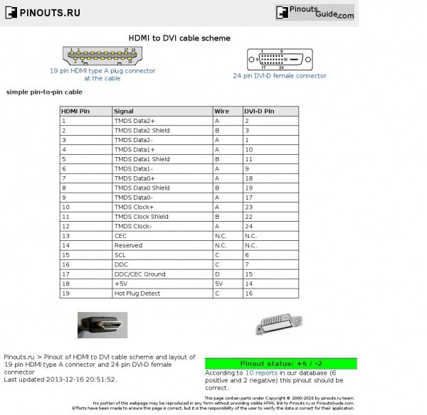
HEC is a high-speed two-way data link for video, audio, data and Ethernet communication. ARC allows HDMI connections to send audio information back to the source for playback, e.g., a TV can send audio to an AV receiver to hear on a surround sound speaker system. Type C Mini HDMI connectors also have 19 pins. HDMI Pinout Diagram: Pin 1: TMDS Data 2+ Pin 2: TMDS Data 2 Shield Pin 3: TMDS Data 2- Pin 4: TMDS Data 1+ Pin 5: TMDS Data 1 Shield Pin 6: TMDS Data 1- Pin 7: TMDS Data 0+ Pin 8: TMDS Data 0 Shield Pin 9: TMDS Data 0- Pin 10: TMDS Clock+ Pin 11: TMDS Clock Shield Pin 12: TMDS Clock- Pin 13: CEC (Consumer Electronics Control)

Dvi To Vga Pinout Diagram
Pinout P1 (19P HDMI F) P2 (20P MINITEK) 325mm HDMI Female Panel Mount Connector Label HDMI Cable heat shrink 1 2 19 18 CBG145 CTIC-00461 REV 0.05 HDMI Cable Instructions - 5 Pair Cable B CN1 Wire CN2 1 Red 1 3 White (Red Pr) 3 2 Black (Red Pr) 5 4 Brown 7 6 White (Brown Pr) 9 5 Black (Brown Pr) 6 HDMI connector pinouts. The above diagram shows a typical Type A pin configuration. Individual pins can carry either data signals, clock signals, low voltage power, control signals, CEC, or HEC. HDMI Cable Types. HDMI cables are available in several types: HDMI Category 1 - Standard Speed Cables: Standard (Category 1) - basic HDMI cable


