A Mercury Marine ignition switch wiring diagram can help you diagnose any electrical issues within your boat's ignition system. An ignition switch wiring diagram will provide the boater with an easy-to-understand overview of the process for replacing or repairing the ignition switch and associated components. The wiring diagram will break. Ignition Switch with Key SWITCH KIT-IGN 87-88107A5. Satisfaction rating 5 out of 5 ( 29 Ratings ) $67.63 $72.72. You save $5.09. (7%)

Ignition Switch Wiring Diagram For Boat
6,027. Jun 18, 2008. #2. Re: mercury 6 wire ignition wiring diagram w/ push to choke. Somewhere in the eighties mercury standardized their wire color codes, 1996 would fall under that standard. Some of the colors you have described do not correspond to ignition switch wiring. Red - Battery voltage (unfused) Can't say that I did the google thing. The boat is a 1988 Mako, and no doubt the harness and switch (1 piece) is OEM to the boat. My Mercury 2004 Shop manual for the outboard currently outback (115 4-Stroke) did not have a wiring diagram for the ignition switch. Well, I manage to get it working, but it's an emotional journey of ups and downs. The Mercury Marine Ignition Switch Wiring Diagram provides a complete overview of your boat's electrical system. It includes detailed instructions on how to wire up every component in the system, including the starter, main power source, and all the switches and wiring associated with the ignition system. It also contains detailed information.
Mercury Outboard Ignition Switch Wiring Diagram Wiring Site Resource
Before you begin the wiring process, it is essential to gather all the necessary tools and materials. You will need a wire stripper, crimping tool, electrical tape, and of course, the Mercury 6 ignition switch itself. The switch should come with a wiring diagram that outlines the specific connections needed. Make sure to read the diagram. MERCURY WIRING DIAGRAMS. The linked images are printable but may print across more than 1 page (in order to be legible). Most models also have black-&-white-only. Ignition & External Wiring Diagram MercElectric SwitchesStarter & Ignition types thru 1969 Merc Model 900-1150-15001976-78 Wiring. astroglass_81. "I want to see if someone can give me some info on a wiring diagram for a Mercury Ignition Switch Part# 87-88107A5. The original switch has terminal markings, new switch is molded in plastic, and I cant tell which terminals the molded wires come from. They are color coded, but the wires in the control are kinda faded. Unlike most diagrams that show components, a wiring diagram for a Mercury Outboard Ignition Switch will provide a visual representation of each part of the electrical system. This type of diagram will show the connection points between each component and the power source (usually ground), as well as showing how the components are connected to.

Mercury 115 2 Stroke Wiring Diagram 👈
MERCURY/MARINER COMMON WIRING COLOR CODES : WIRE COLOR(S) FUNCTION: COLOR SAMPLE : BLACK: GROUND: BROWN: Reference Electrode MerCathode System : ORANGE:. Ignition (Switch) to 12 Volt Positive : TAN: Temperature Switch to Warning Horn and/or Temperature Sender to Temperature Gauge : TAN / /BLUE STRIPE : The Ignition switch dry rotted and broke. I tryed replacing it the Mercury switch EL076020 IGN switch (this replaces 87-88107 and 87-88107A5 switch). The wire termanal on the old switch does not match the new one. OLD switch A, M, B, S, C. NEW SWITCH A, M, B, M, C, I, S. if this is the correct switch please help with the correct wiring,color.
Sierra MP41070-2 3-Position Magneto - Off-Run-Startby Amazon.comhttps://amzn.to/3leixtBNeed to replace your ignition switch? I did with a 90HP Mercury outboa. Capt. Chris of Buzzards Bay takes a look at a common Evinrude/Johnson ignition switch with integrated clip-on safety lanyard (BRP part No. 5005801). You'll s.

I have 1974 65 hp mercury motor that sparks sometimes and next time no
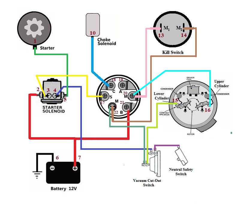
The diagram consists of three parts. First, there is the power or main wire. These are the red and black wires that run from the battery to the kill switch. Next, there is the ground wire. This wire connects to the grounding point on the engine block. Finally, there is the hot wire. This connects the kill switch to the ignition system. Our best advice is not really only look from the diagram, yet understand how the components operate when within use. Mercury Ignition Switch Wiring Diagram Source: tse1.mm.bing.net. Mercury Ignition Switch Wiring Diagram Source: mainetreasurechest.com. Before reading the schematic, get common and understand each of the symbols.
