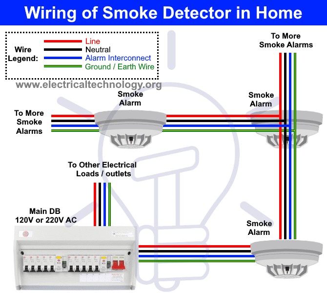
A hardwired smoke alarm installation involves wiring one of the smoke detectors (closest to the voltage source) to a 120 VAC breaker in the main electric panel or tapping from a 120 V electrical box, wiring it using a 14/2 cable with a black (live), a white (neutral), and a ground wire, as shown by the diagram in Figure 5. Plug the wire harness into the back of the smoke alarm. Open the battery compartment on the alarm. Insert the correct type of battery (usually a 9-volt battery), being careful to position it so positive contact meets positive contact and negative contact meets negative. Close the battery compartment.

FDAS Fire Detection And Alarm System Company, Contractor, Installer
Typical household smoke alarms use a black wire for detecting smoke, a white wire as the common conductor and a red wire that communicates with other smoke d. Wire and install a new smoke detectors in both the finished and unfinished sections of the basement. 120VAC power for the smoke alarms will provided by a new branch circuit from an existing junction box on a continuous (i.e. non-switched) circuit. The new work is indicated by the green box in this wiring diagram: More often, though, hardwired smoke detectors are installed by splicing into a general lighting circuit or outlet circuit. Either a 15-amp circuit (wired with 14-gauge wire) or a 20-amp circuit (wired with 12-gauge cable) is acceptable for powering hardwired smoke detectors. Wiring the smoke detectors is fairly straightforward for an. This video teaches you how to wire and interconnect smoke detectors. All homes need smoke detectors, you must also wire your smoke detector on the same circu.

Types of Fire Alarm Systems and Their Wiring Diagrams
Before, Wiring a Smoke Detector, watch this to learn step by step for beginners how to make safe connections, HOW to WIRE a junction box, WHEN to use 14/2 or. Use the stud finder to make sure that the intended position is clear of ceiling studs. After shutting off power to the area, cut a hole in the ceiling with the ceiling hole saw. 3. Run Starter. Electronic "noise" may cause nuisance alarms. † Smoke alarms are not to be used with detector guards unless the combination (alarm and guard) has been evaluated and found suitable for that purpose.. 3. INSTALLATION INSTRUCTIONS WIRING REQUIREMENTS † This smoke alarm should be installed on a U.L. listed or recognized junction box. Connect the wiring harness with the black, white, and red wires coming through the nearest electrical box. Step 7: Put It All Together. Once the smoke detectors have been wired, attach the mounting plate to the electrical box with screws. Then, the wire harness is attached to the back of the smoke alarm.

kidde smoke alarm wiring diagram
Summary of Contents for Kidde i12060A. Page 1 Refer to the User's Guide supplied with each Kidde product for interconnect com- patible models, brands, and devices. Refer to the wiring instructions in section 3 for NFPA initiating device limits. Page 2 This alarm detects products of combustion using the ionization technique. way to insure proper operation of 2-wire i3 smoke detectors (2W-B, 2WT-B, 2WTA-B, or 2WTR-B) on Style D IDC's is to use a 2W-MOD2 module. Refer to the 2W-MOD2 installation manual, document D500-46-00, for Style D wiring diagrams. The 2W-MOD2 installation manual may be downloaded from the System Sensor web site at www.systemsensor.com.
The smoke alarm, NM-B 14/3 cable roll and old work electrical box are shown here: Kidde/FIREX Smoke Alarm Model # PI2010 and NM-B 14/3 Wire Smoke Alarm Wiring Diagram. The NM-B 14/3 branch circuit for the new smoke alarm was connected to the octagonal ceiling box in Part 2. The NM-B 14/3 wire will be strung along the floor joists to the. Smoke Alarm Wiring Diagram: Junction Box Splice for NM-B 14/3 Cable Shutoff the Electricity. The electricity must be shutoff at the circuit breaker panel before working on the wiring to avoid shock, injury and/or death. If you are uncomfortable working with electricity, hire a licensed electrician. Verify the electricity is Off by testing the.

10 Fire Alarm Installation Wiring Diagram Cable For Smoke Alarms Fire
Kidde Smoke Detector Wiring and Installation. Step by step guide to add additional smoke detectors to your house and have them linked together. This is in th. Check Push-to-Test button. A constant green light indicates the smoke alarm is receiving 230V AC, 50Hz power. A red flashing LED about once every 5 minutes verifies operation. For models KF10, KF10LL, KF10R, KF20, KF20LL and KF20R the red flashing LED also verifies that a working battery is present.


