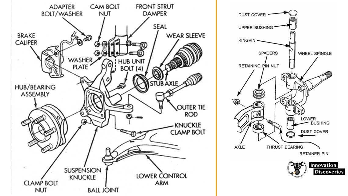
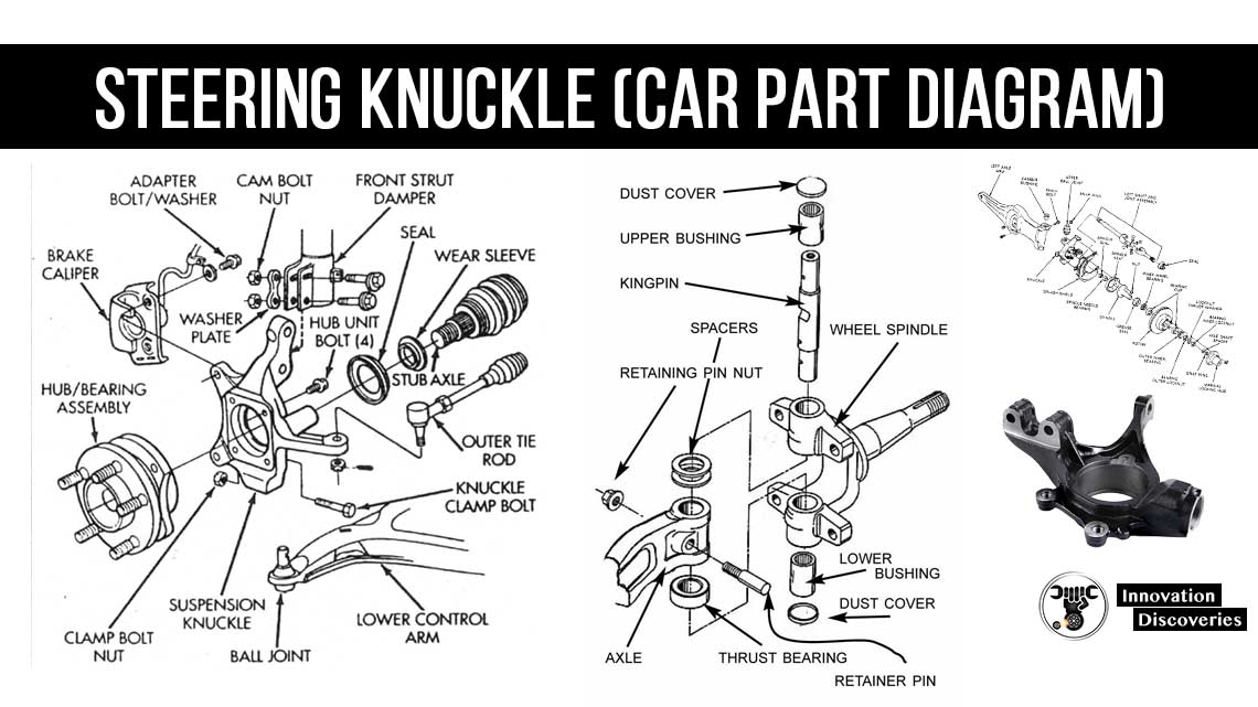
Watch on MOOG® offers pre-assembled steering knuckle assemblies to reduce assembly and installation time by up to 60% while offering MOOG® quality and reliability. In automotive suspension, a steering knuckle or upright is that part which contains the wheel hub or spindle, and attaches to the suspension and steering components. [1] The terms spindle and hub are sometimes used interchangeably with steering knuckle, but refer to different parts.

(a) A drawing of the position of a steering knuckle in the steering and
Steering System: It's Working, Types, Parts, Steering Gears with Diagram Last Updated on: November 9, 2021 by Saif M In this post, you'll learn about the steering system and its working, wheel alignment, types of the steering system with parts, function, diagram, and types of steering gears. Steering System Contents show 74 Share 20K views 7 years ago Tech Tips To learn more about steering and suspension repairs, including servicing the steering knuckle and ball joint, visit Garage Gurus fmgaragegurus.com.. When to Replace Your Steering Knuckles - In The Garage with CarParts.com Knowing when to replace your vehicle's steering knuckle can spell the difference between a comfortable ride and one that handles poorly and is potentially dangerous. Steering Knuckle Steering Knuckle Types: Steering Knuckle with spindle Steering Knuckle with hub

Steering knuckle (Car Part Diagram)
The steering tie rod diagram typically consists of various components, including the inner and outer tie rods, the steering knuckle, and the ball joints. Each of these elements plays a vital role in ensuring the stability and control of the vehicle while navigating corners or making steering adjustments. The fatigue analysis showed that the steering-arm portion of the knuckle failed when it experienced cyclic load as shown in Figure 4(a).The steering arm was treated as a cantilever beam for. The steering system converts the rotation of the steering wheel into a swivelling movement of the road wheels in such a way that the steering-wheel rim turns a long way to move the road wheels a short way. The system allows a driver to use only light forces to steer a heavy car. How A Steering Knuckle Helps Your Vehicle Change Direction. The top and bottom arms of the steering knuckle attach to the suspension system via pivots called "ball joints". The ball joints let the knuckle pivot left or right. They also keep the knuckle in a vertical position. The steering knuckle also has a lateral arm that connects to a tie rod.

Steering knuckle (Car Part Diagram)
1. Steering wheel 2. Steering column or shaft. 3. Steering gear 4. Drop arm or pitman arm 5. Ball joints 6. Drag link 7. Steering arm 8. Stub axle 9. Left spindle and kingpin 10. Left tie rod arm 11. Track rod or tie-rod 12. Right tie rod arm, spindle and kingpin 13. Steering stops. steering system components 1.Steering wheel: How a Typical Front End Suspension Works (Plus Diagram) - In The Garage with CarParts.com Understand how a typical front end suspension works and what to do in case you need a front end repair in this helpful article. Read more.
The steering knuckle is joined to the steering knuckle support by a kingpin. On vehicles after the mid-1950s, ball joints connect the control arms to a steering knuckle assembly which combines the steering knuckle and support into one unit. In most North American cars the steering linkage consists of three parts. The Pitman arm transmits gear. The steering arms turn the steering knuckles and the wheels which are pivoted left or right on the front end suspension. There are four common manual steering gears in use. The worm and sector, worm and roller, recirculating ball steering and the rack and pinion. In the worm and sector style the worm is connected at the end of the steering shaft.

Repair Guides Front Suspension Steering Knuckle And Hub Assembly
Disconnect the steering tie rod from the knuckle. Remove the 8 bolts that hold the oil seal retainer (#22 on diagram) to the knuckle casting. Remove the retainer and seal. Note that several type seal designs were used, all accomplishing the same result. Remove the 4 bolts retaining the lower pivot pin bearing cap (#13 on diagram). The design of Steering Knuckle component is done with the help of Computer Aided Engineering (CAE). Steering Knuckle model is prepare in Creo(Pro-E) 2.0 and the static analysis is done in ANSYS WORKBENCH15.0 by constraining the steering knuckle and applying load on steering knuckle due to caliper mounting, longitudinal reaction, vertical.


