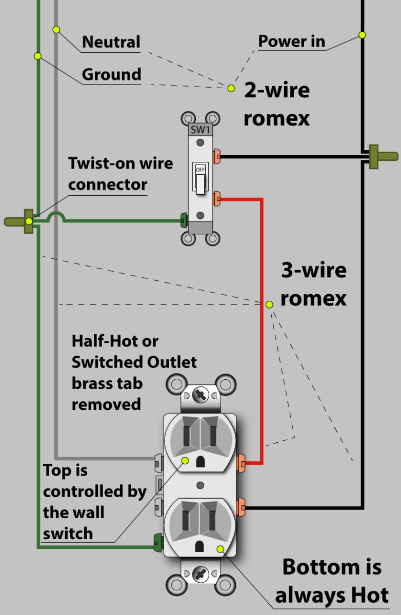
This diagram illustrates the wiring for a split half outlet controlled with a switch loop. The tab connecting the hot terminals on the receptacle is removed and the source hot is connected to the bottom half. The source neutral is connected to one of the neutral terminals on the receptacle. The diagram below shows the power coming from the circuit breaker panel. The same wiring diagram can be used if the power comes from another outlet connected to one of the depicted outlets. Switched outlet diagram with hot and a neutral entering the switch box. In the wiring diagram above, a hot and a neutral enter the single pole switch box .

Light Switch And Outlet Wiring Diagram Database
In this simple wiring diagram, the combo switch & outlet is connected to the 120V AC supply through CB. The break away fin tab is intact therefore, line (hot) is connected to the (only) one brass terminal on line side. The neutral is connected to the neutral silver terminal. The switch load brass terminal and neutral is connected to the light bulb. Estimated Cost: $20 Wiring electrical outlets (properly called receptacles) and switches involve many of the same basic techniques. Making safe, long-lasting connections requires properly preparing the circuit wires that will connect to the device and securing each wire to the correct terminal. What You'll Need Equipment / Tools 1 / 24 Buying a Dimmer Switch Dimmer switches are available in many styles and configurations, including slides, knobs and touch-sensitive dimming mechanisms. However, check these key things: Capacity (how many lights it can control). The capacity will be measured in watts. Switch Outlet Wiring Diagrams Summary: This switched outlet electrical wiring diagram shows two scenarios of wiring for a typical half hot outlet that can be used to control a table or floor lamp. © By: Dave Rongey Understanding Switched Outlet Wiring for Home Electrical Applications Electrical Wiring Video How to Wire a Light Switch

Electrical Wiring Diagram For Spacious Switch Wiring Electricity
Wiring a Grounded Duplex Receptacle Outlet. This is a standard 15 amp, 120 volt wall receptacle outlet wiring diagram. This is a polarized device. The long slot on the left is the neutral contact and the short slot is the hot contact. A grounded contact at the bottom, center is crescent shaped. Don't use this receptacle when no ground wire is. What Kind of Wiring Do You Need for a Switched Outlet? The National Electric Code requires that all lighting switch boxes contain a "neutral," which is an electrical term for a grounded conductor (not to be confused with a ground wire). In your outlet, it is the white wire that terminates on the outlet. Author: Terry Peterman Category: Switches & Receptacles, Wiring Diagrams Single Pole Switch to an Outlet Click on Image for Larger How to wire a switched outlet with a single pole switch is illustrated in this wiring diagram. This diagram shows the wiring for a new outlet added from a light switch. The switch must have an always-hot wire for the source and a neutral wire must be present for the return path. This receptacle can not be added to a switch wired as a loop to control the light.

Outlet Switch Wiring Diagram Esquilo.io
The following wiring diagrams show that multiple outlets are wired to a single pole (SPST switch, one-way or two way in US) switch. As shown in the fig, the switch is firstly installed in the wiring the hot wire from switch feeds all the other parallel connected outlets hence, the outlet ON/OFF operation can be controlled through the switch. A switch and outlet combo can be configured in several ways. Switch can control the light only. Switch can control the light and outlet. Switch and the outlet can have different lines in. The following diagrams show each wiring configuration. Ground connection diagram is shown separately.
Learn how to wire a switch/receptacle combination device with these detailed wiring diagrams. Wiring diagrams for the different applications of duplex switch and receptacle combination devices are shown. Author: Terry Peterman Category: Switches & Receptacles, Wiring Projects If you want to help support Shannon to produce more videos like this, visit https://www.house-improvements.com/donateShannon from https://www.house-improveme.

Switch Outlet Wiring Diagram Wiring Diagram
Switched Outlet Wiring Diagram Take a closer look at a switched outlet wiring diagram. You may want to have a plug that has a lamp plugged in and is operated by a switch while keeping the other outlet hot. If that is the case, pick the diagram that is most like the scenario you are in and see if you can wire your outlet. In switch receptacle combo wiring, the unit consists of a switch and an outlet that share the same electrical circuit. This means that power is supplied to both the switch and the outlet simultaneously. The switch controls the flow of electricity to the outlet, allowing users to turn the outlet on or off as desired.


