Here we collected the standard engineering drawing abbreviations and symbols to provide help for users. Why Use Abbreviations and Symbols in Engineering Drawings A good design drawing can indicate all the details needed to produce a mechanical CNC milling part in an easy way. Engineering drawing abbreviations and symbols are used to communicate and detail the characteristics of an engineering drawing. This list includes abbreviations common to the vocabulary of people who work with engineering drawings in the manufacture and inspection of parts and assemblies.

Symbols For Tattoos Que la historia me juzgue
Geometric tolerances are specified using symbols on a drawing. Currently, we have 16 symbols for geometric tolerances, which are categorized according to the tolerance they specify. True Position Theory (Size Value in Rectangular Frame) Classification and Symbols of Geometric Tolerance Characteristics GD&T Flatness is a common symbol that references how flat a surface is regardless of any other datum's or features. It comes in useful if a feature is to be defined on a drawing that needs to be uniformly flat without tightening any other dimensions on the drawing. Because there's not a lot of space on the drawing, engineers use symbols and abbreviations to communicate specifications and dimensions. Symbols are universal and allow anyone to use the engineering drawing to replicate the object regardless of the language they speak. 1. Check numbers in circles for keynotes. Engineering Working Drawing Basics is a pdf document that introduces the fundamental principles and practices of engineering drawing. It covers topics such as types of drawings, symbols, dimensions, tolerances, and views. It is a useful resource for students and engineers who want to learn or review the basics of engineering drawing.

Tutorials for Drawing Symbols
There are literally hundreds of engineering drawing symbols and they're used in a variety of ways. For example, engineering symbols are used in technical drawings to convey the specific geometry and other details about pieces of equipment or components. To limit errors caused by personal interpretation, engineering drawings and diagrams are. Figure 1. Equivalent Symbol and Note 1.2 The symbols are presented in two groups for easier use of this section as a reference. General dimensioning symbols are shown first. Some of these symbols are also used in tolerance specifications. The second set of symbols are used for toler-ances. Engineering Drawing Abbreviations and Symbols. To read an ED, you must first become familiar with the various symbols, abbreviations, and diagram basics. Once you familiarise yourself with these features, you'll be able to trace the lines in a system to understand specific components and the overall function in the case of PFDs and P&IDs or. Symbols: Need to Know for Dispelling Uncertainty in Drawings . The following is a short list of symbols that normally appear on a Technical Drawing and need understanding. We offer you our tips which we believe are useful for dispelling uncertainty by comparing the symbol with its graphic representation.

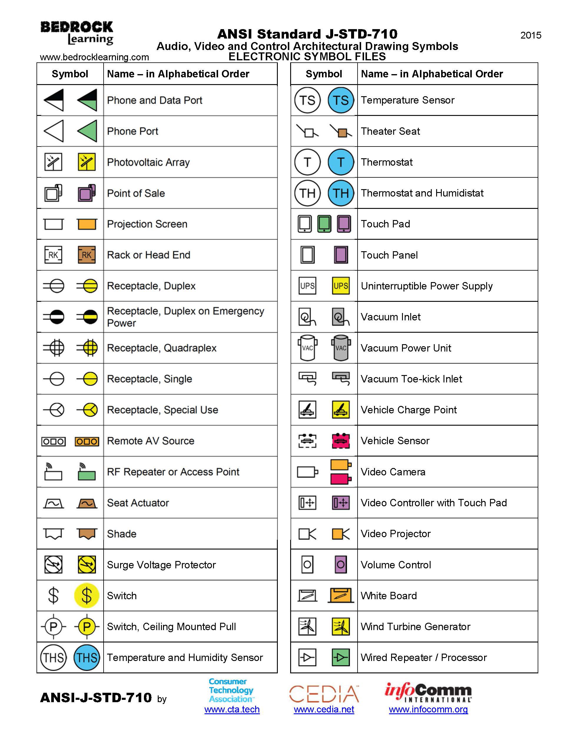
ANSI Standard JSTD710 Architectural Drawing Symbols Bedrock Learning
There are 7 aspects of the GD&T methodology that we will discuss, these include: Views, Dimensions, Tolerances, Symbols, Datum's, Feature Control Frames & Title Blocks. Drawing Views. The first tool in your engineering drawing toolbox is the drawing view. Drawing Views are simply the representation of your component from multiple perspectives. What is Surface Finish? Surface finish is the term used to describe the texture of a surface, and it is sometimes used interchangeably with the term surface texture. Requirements for surface finish are frequently found on technical drawings for mechanical parts, particularly where parts fit together tightly, move against each other, or form a seal.
Most new drawings will have an isometric view to guide you. You can use the Bill of Materials to find the components in the drawing in order to understand the role they play in the assembly. Remember that reading an engineering drawing can take a long time, depending on the complexity of the assembly and the experience of the reader. Structural drawings are a series of pages which explain and illustrate the structural design intent of a building or structure. The aim of a good set of structural drawings is to provide the reader with enough information to: Construct that building or structure if you are a contractor

Pentacle Drawing at GetDrawings Free download
A simple drawing with GD&T datum symbols. Image Source. GD&T positions every part within a Datum Reference Frame (DRF). Some say the DRF is the most important concept in geometric positioning and tolerancing because it provides the skeleton or frame of reference to which all requirements are connected. For that reason, we want to start early. drawing to specify information for a specific feature of a component or assembly. The feature being referenced is indicated through the use of a leader line. The leader line points to the feature in question and terminates at the note. One common example of a local note is the specification of the size dimension of a hole feature.


