Learn how to install the Viper alarm system in your vehicle with this detailed manual. The guide covers the wiring, programming, and troubleshooting steps for the N426V model. You will also find useful tips and safety precautions for using the remote control. Viper is the world's best selling vehicle security and remote start brand. We use cutting-edge technology to make sure you are in control, providing range and features you can count on every time.. Viper: 2351 J. Lawson Blvd. Orlando, FL 32824 . What Our Customers Say. Had this alarm installed in my Camaro z28 and could not be happier, my.

Diysity Viper 300 Esp Car Alarm Wiring Diagram
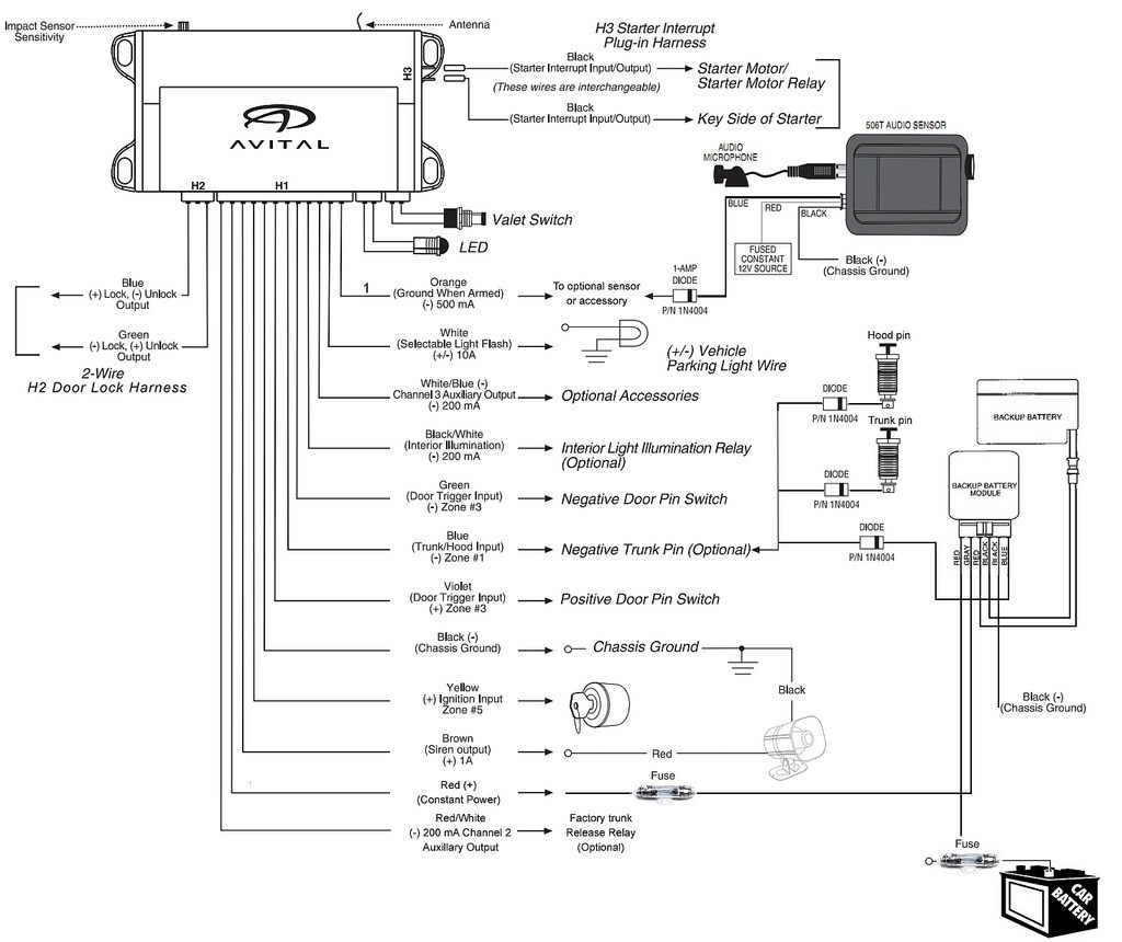
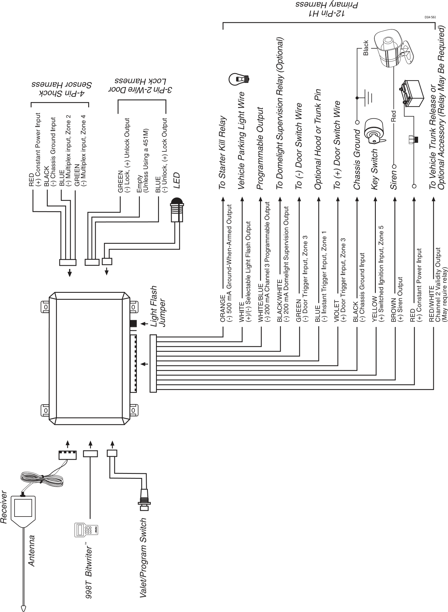
As far as the 6 pin harness goes, obviously the red wires goes to 12v constant, black is grounded, brown goes to the siren (+), white goes to the parking light that still doesn't work, and I read that I don't need the white/brown or orange wire. Let me know if any of that sounds wacky to you. Any help is greatly appreciated. Following the Viper alarm system's wiring diagram, carefully connect the wires to their respective components. Once all the wires are connected, it is important to test the system to ensure everything is working correctly. This involves activating the alarm system using the remote control and checking if the sensors and sirens respond. 24 GREEN/WHITE (-) 200mA FACTORY ALARM ARM OUTPUT * Connect this wire to one of the wires on the provided Remote Start Shutoff Switch. The other wire on the switch connects to the (-) Parking Brake wire in the vehicle. The switch must be in the ON position for the remote start to work. Do you want to install a Viper security and remote start system in your vehicle? Download the installation guide from the target url and see page 5 for the wiring diagram and important safety precautions. This guide is in English and covers the model N5X06. You can also find other guides for different models and languages from the related webpages.

Installing a Viper alarm/remote start, need a bit of help with the
Dei viper 5000 car alarms: owners guide (61 pages) Car Alarm Viper 5501 Owner's Manual. Remote start and keyless entry system (60 pages). Page 26: Door Lock Wire Diagrams BLUE (-) 200mA STATUS OUTPUT This wire supplies an output as soon as the module begins the remote start pro- cess. It can be used to activate a bypass module or power the. View and Download Directed Electronics Viper 350HV installation manual online. Viper 350HV car alarm pdf manual download. Sign In Upload. Download Table of Contents Contents. Add to my manuals. Delete from my manuals.. Page 4: Primary Harness Wiring Diagram NOTE: If using the H1/1 ORANGE wire to activate an add-on accessory such as window. View and Download Viper 500+ installation manual online. car security. 500+ car alarm pdf manual download.. Door Lock Wiring Diagrams. Transmitter/Receiver Learn Routine.. Dei viper 5000 car alarms: owners guide (61 pages) Car Alarm Viper 3000 Installation Manual. Viper 3000 (39 pages). Connect this wire to an optional domelight supervision relay as shown in the following diagram: WIRE This wire supplies a (-) 200 mA output for 30 seconds when the system is disarmed, and when the ignition is turned off (programmable On/ Off). It will pulse continuously during the alarm trigger duration.

⭐ Viper Alarm Wiring Diagram ⭐
Dei viper 460xv car alarms: owners guide (37 pages) Car Alarm Viper 5806V Owner's Manual. Auto security systems (19 pages) Car Alarm Viper 3100 Owner's Manual.. Page 5 H1/3 BLACK/WHITE-1 Domelight Supervision Input This wire determines what the output polarity of H1/4 will be. If the door pin circuit is negative, connect to chassis ground. Wiring Diagram 5X05 Remote Start 10-pin Harness Main 5-pin Harness Door Lock 3-pin Harness Light Flash Polarity Jumper (-/+) Onboard Thermistor Temp Sensor. 24 GREEN/WHITE (-) 200mA FACTORY ALARM ARM OUTPUT * Connect this wire to one of the wires on the provided Remote Start Shutoff Switch. The other wire on
350 Plus. Installation Guide. NOTE: This product is intended for installation by a professional. installer only! Any attempt to install this product by any person other. than a trained professional may result in severe damage to a vehicle's. electrical system and components. ©2008 Directed Electronics, Vista, Ca. N3105V- 2008-12. View and Download Viper 5101 installation manual online. Remote Start Keyless Entry. 5101 remote starter pdf manual download.. Auxiliary harness (H2) H2/1 LIGHT GREEN/BLACK (-) 200mA FACTORY ALARM DISARM OUTPUT This wire sends a negative pulse every time the remote start is activated , chan- nel 2 is activated (programmable on/off) or when.

Viper Alarm 350HV Wiring Diagram And Installation Guide
With the Viper Alarm 3105v, you can enjoy the peace of mind of knowing that your property is secure and monitored 24 hours a day. The Viper Alarm 3105v Installation Guide offers detailed guidance on how to install the device, connect it to your home's existing wiring, and configure it to meet your specific needs. Use the wiring diagram that comes with the Viper system to ensure that everything is hooked up properly. Finally, test the system by activating it to make sure that it is working correctly. By following the steps in this guide, you should be able to install your Viper 3105v system without any issues.


