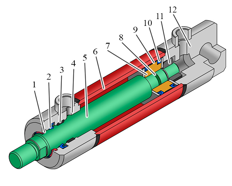
Description Hydraulic cylinder design. How does the hydraulic cylinder work? Гидравлика и пневматика 1.7K Likes 2018 Apr 18 How does the hydraulic cylinder work? A hydraulic cylinder has. A simple diagram below helps explain the mechanics of the process -- as fluid enters a chamber more force is applied to push or pull the piston rod in or out of the cylinder and, in turn, pivot, push, or pull the component the cylinder is connected to. Hydraulic cylinders come in two types: single acting and double acting.

Anatomy Of A Hydraulic Cylinder
A hydraulic cylinder is a mechanical actuator that gives a unidirectional motion through the force of the hydraulic liquid. It is also referred to as a linear hydraulic motor. It has a wide area of applications, ranging from the construction industry to mechanical machines. Without this, we can not see the enormous development of the nations. A hydraulic cylinder is the actuator or 'motor' side of the system. The 'generator' side of the hydraulic system is the hydraulic pump which brings in a fixed or regulated flow of oil to the bottom side of the hydraulic cylinder, to move the piston rod upwards. The piston pushes the hydraulic oil in the other chamber back to the reservoir. Barrel The first major part of a hydraulic cylinder is the barrel, which is a smooth cylinder that keeps pressure inside the cylinder. Designed internally to reach the correct diameter, most cylinder barrels have exterior finishes between four and 16 micrometers. Additionally, there are two major types of barrels: single-acting and double-acting. Parker Hannifin Corporation is a leader in industrial hydraulic cylinders, offering a wide range of products and solutions for various applications. This pdf catalog provides detailed information on the features, specifications, dimensions and materials of Parker's industrial cylinder series. Learn how to select the best cylinder for your needs and discover the benefits of Parker's quality and.

Hydraulic cylinder, double and single acting, plunger and telescoping
A hydraulic cylinder schematic diagram provides a visual representation of the different components and fluid flow paths within a hydraulic cylinder system. By studying these diagrams, engineers and technicians can gain valuable insights into the functionality and performance of hydraulic cylinders. Learn the fundamentals of hydraulic systems and components with Parker's training course on basic hydraulics. This PDF file covers topics such as hydraulic principles, symbols, pumps, valves, cylinders, motors, and maintenance. Download it for free and enhance your skills and knowledge in industrial hydraulics. Hydraulics engineers regularly encounter these diagrams, but these symbols can be daunting to interpret if you have limited experience with schematics and the fluid power industry. On this page, Carr Lane ROEMHELD provides a comprehensive table outlining the definitions of each symbol used in a hydraulic diagram. The hydraulic cylinders on this excavator operate the machine's linkages. Hydraulic cylinders in a hot press of a particle board machine. A hydraulic cylinder (also called a linear hydraulic motor) is a mechanical actuator that is used to give a unidirectional force through a unidirectional stroke. It has many applications, notably in construction equipment (engineering vehicles.

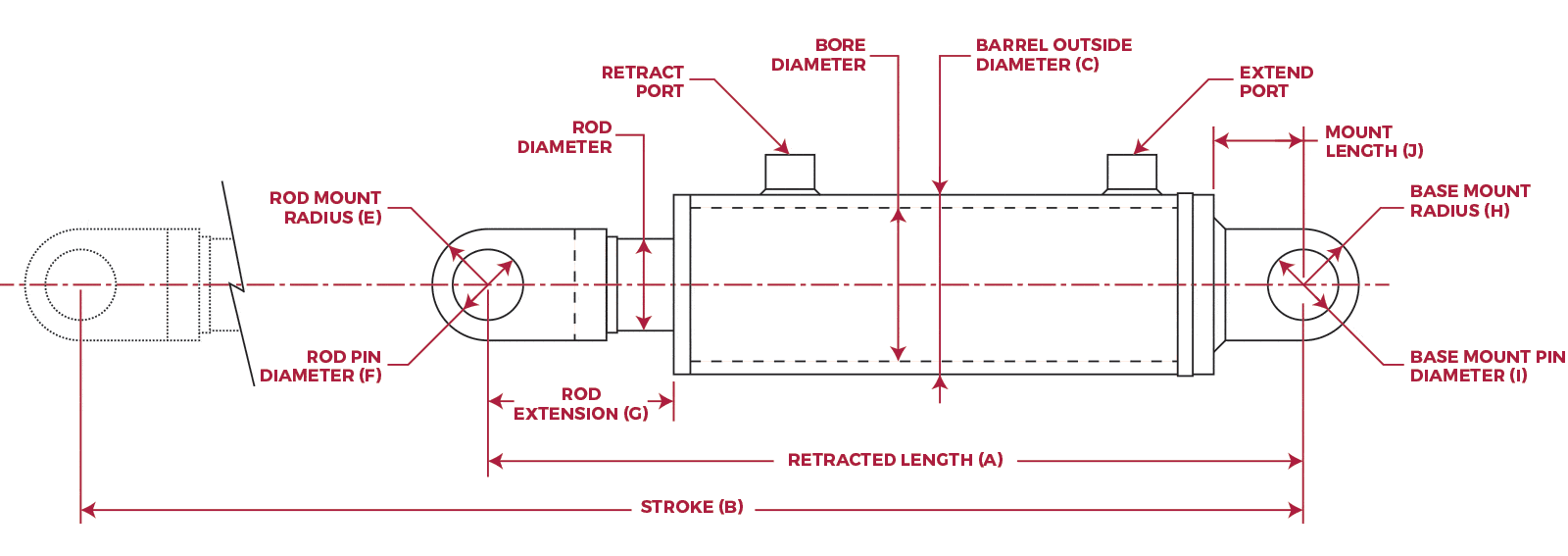
How to Measure Cylinders Hydraulic Cylinder Measurements
Hydraulic cylinder design. Construction and working principle of the hydraulic cylinder. Components of the hydraulic cylinder: rod, piston, pipe, caps, seals Fτ = P∏ (r12 - r22 ) Where: Fτ is the resultant force. P is the pressure distributed load on the surface. ∏ is pi, approximately equal to 3.14159. r1 is the radius of the piston. r2 is the radius of the piston rod. In hydraulic cylinders, the force can easily be multiplied or divided throughout the system.
Graphic Symbols: Following diagram illustrates standard ANSI (American National Standards Institute) graphic symbols for use in circuit diagrams. Six of the more often used are shown: Standard Double-Acting Double-End-Rod Ram-Type, Single-Acting Single-Acting Single-Acting, Spring Return Telescopic Series 2AN Cylinders Piston Seal Kits 46-47 Rod Seal Kits 48-49 TS-2000 Seal Kits and Gland Replacement Procedure 50-51 Series 3H Large Bore Hydraulic Cylinders Parts Identification 52-53 Seal Kits 53 Series 3H 7" & 8" Bore Hydraulic Cylinders Parts Identification and Maintenance Instructions 54 & 55 Series HMI Cylinders Parts Identification 56-57

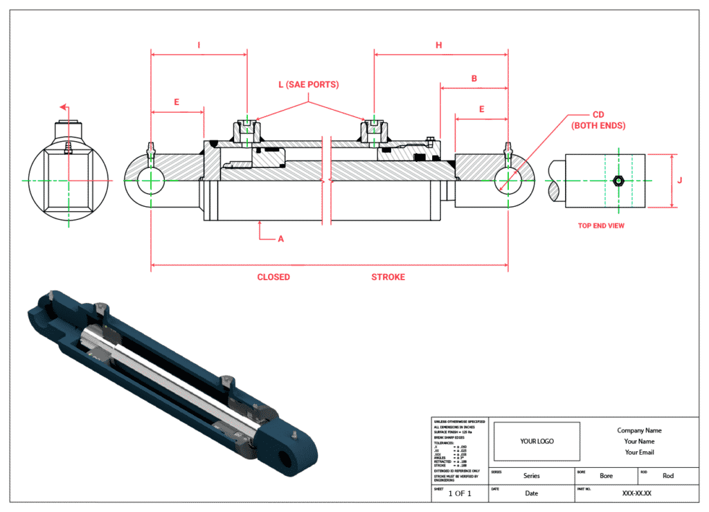
PreEngineered Cylinder Drawing Application Aggressive Hydraulics
A hydraulic cylinder has eight basic components; the clevis, gland, port (s), barrel, rod, piston, the end cap, and the seal. When combined, these parts allow the hydraulic cylinder to pressurise fluid that mobilises a piston to generate power for a machine. 1. Identifying the line types In a hydraulic schematic, each line type has a unique meaning. In addition, colors can be added to indicate purpose of the line. In the figure below, all of the basic line types are shown. The basic line is a solid line that represents a working pressure hose or tube.


