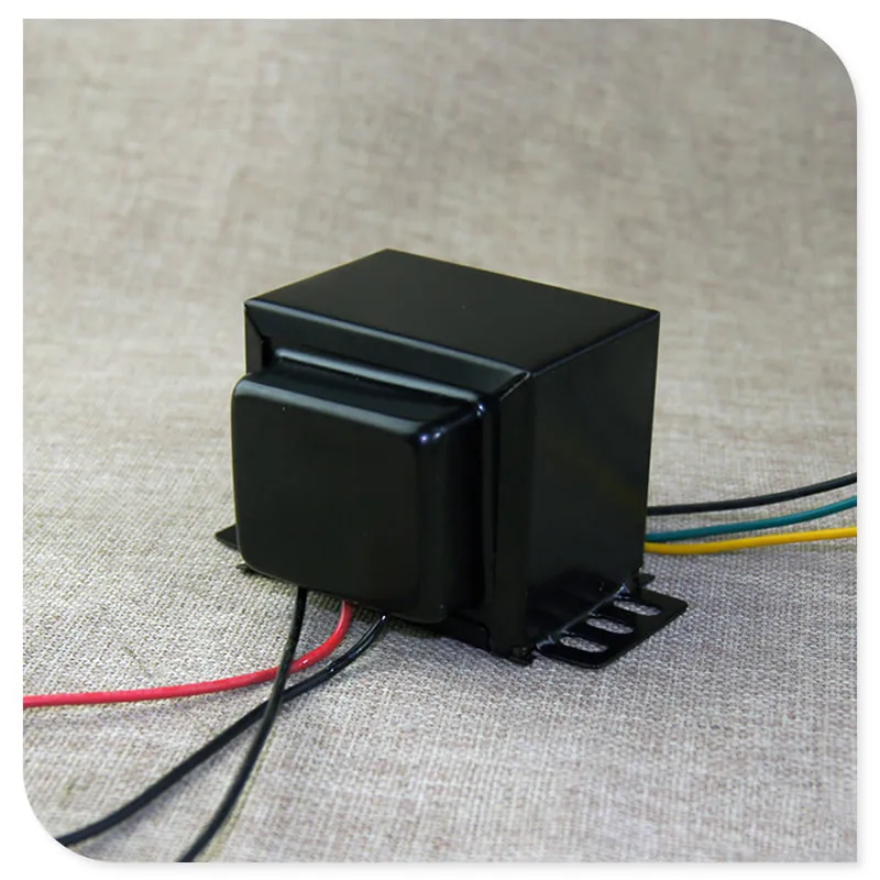
No matter what you love, you'll find it here. Search Output Transformer 6v6 Push Pull and more. Looking for Output Transformer 6v6 Push Pull? We have almost everything on eBay. This 6V6 amp was built following the push-pull (PP) EL84 / 6V6 Dynaco A-410 output transformer schematic. There are a few minor deviations from the original schematics. Instead of Dynaco transformers, Hammond 1608A audio output transformers and a Hammond 272HX power transformer were used.

50W Output Transformer 6L6 EL34 4x EL34 Vox AC30 4x 6V6 Reverb
#1 I'm DIY building the RCA SP10 push pull 6V6 10 watt amp and I have a question about what output transformer to use for best sound. Wondering if some of you will more experience can help out here. I understand some of the design rules - but then there seems to be a lot of "bending" of said rules. Only $34 shipped. They give Mercury Magnetics a run for the money. These transformers are made in China but the quality specs are really good. Anyway here's a clip of the amp after the upgrade. I wish I had a "before" clip. The datasheet for a 6V6 power tube (as used in a Fender Deluxe Reverb amplifier) shows that the load resistance should be 5000 to 8500Ω; with an optimum power output and distortion at 6000Ω. The output transformer has a primary impedance of 6600Ω, with a center tap. If, in the push-pull configuration, each tube works into half of the primary. 2018-11-10 5:57 pm. #6. Switch the 6SL7 to a 6SN7, and change the bias resistor and plate resistors. You will need 3x the drive that way, but if you have a line amp you can drive it. Otherwise reduce the GNFB. Might be something fun to play with, but as pointed out it needs modification. huggygood. Member.

23wpushpulloutputtransformer6P16P6P6V66P14FU296AQ56F6tubeampoutputaudio.jpg
Step 1: Circuit Design History I did not design the power amp circuit. However I did design the power supply. The origin of the power amplifier design came from the schematic below, which came from the 1959 RCA RECEIVING TUBE MANUAL Tech Series RC-19 Ask Question Step 2: Power Supply Schematic Fender tended to bias their push-pull amps cool from the factory at around 50 to 60%. In the 5F6A Bassman the output transformer center tap can be accessed at either terminal of the Standby Switch or where the output transformer center tap lead is connected to the circuit board. Note the power tube plates (pin 3). The EL84 (6BQ5) / 6V6 Push-Pull tube amplifier schematic and text below is from the Dynaco Super-Fidelity Output Transformers catalog circulated around 1955. "Figure 3 illustrates a low power circuit (12 watts at less than 1% distortion) which is similar to that used in many of the medium priced commercial amplifiers. Elco Pair (2) Tube Shields EL84 9-pin J-Slot J60-ELCO Vintage Vacuum 1950s-1960sUsed - Good. $36. Functioning set of output transformers from 1960s magnavox console amplifier. I believe Stancore produced these and most of their units. Each output was driven by a pair of 6V6gt power tubes. 6.6k/4k primary/secondary impedance I do not know the.

30W 8K048ohm Pushpull output transformer for6V6 6P6P EL84 W/super linear tap eBay
Push Pull output transformer 8000 Ω to 4 and 8 Ω optimized for EL84, 6V6 pentode and triode strapped applications The Summit series " type B-14 " is a push pull output transformer designed around the EL84 and 6V6 pentode operating in pentode or triode strapped mode: " 15 Watts rms " output power. 6V6 Push-Pull output transformer. 12-14-2022, 07:29 PM. Hey folks, I'm trying to source an output transformer for a pair of 6V6 in Push-Pull config. It needs to be 20Watts and have 4-16ohm taps. Hammond is trying to tell me that their 1645A should do the job, but the primary impeadance is 5K no what you'd expect of 8K for 6V6 Push-Pull config.
The author has plans for a pair of mono-bloc 6V6 push pull amplifiers with Hammond output transformers and DC-DC converts for both heater supply and main HT - all powered from a 19.5 Volt 'laptop brick' switched mode power supply. While looking at ebay, the present amplifier kit caught the author's eye. 6V6 SE UL Test Circuit Schematic. This circuit uses an Edcor GXSE10-8-5K UL transformer as the load for the power tube. The transformer is terminated with an 8 ohm resistive load. For bias adjustment I used a 25W 1 k-ohm rheostat bypassed with a 200 uF capacitor which allowed me to set the bias at each operating point.

Home Improvement Electrical Equipments & Supplies 10K pushpull output transformer with super
#1 6V6 output transformer 08-12-2021, 05:08 PM I would appreciate some help understanding my output transformer's specifications, just to make sure I've wired things correctly in my amp whose OT output is switchable for 1 or 2 6V6's (SE). Its a 90 degree phase shift. The "top" half of the transformer will shift forward by 90, the "bottom" will lag by 90 to make the total of 180 degrees of phase inversion. The speaker output will be 90 degrees shifted from whatever the input is though, so no global feedback. Local can be done though, so unbypassed cathode in the output stage.


