Automotive electrical diagrams provide symbols that represent circuit component functions. For example, a few basic symbols common to electrical schematics are shown as: (1) Switch, (2) Battery, (3) Resistor and (4) Ground. Note the switch symbol displays an open or closed circuit path, which is what an actual switch performs. A car wiring diagram is a map. To read it, identify the circuit in question and follow it to the ground, starting at its power source. Use the legend to understand what each symbol on the circuit means. I have been an auto technician for over twenty years, and I've always loved the electrical side of auto repair.
How To Read Car Diagrams
To read a wiring diagram, you have to trace the flow of power. Start by locating the battery symbol. Then, follow the path from the battery to the ground. Keep an eye out for components like switches, fuses, and relays. Note that fuses and relays prevent too much power from flowing through a circuit. 3. The most commonly used symbols in automotive wiring diagrams are labeled with the letter "A" followed by a number. These symbols indicate the type of component, such as air conditioning, alternator, battery, or starter motor. Additionally, there are separate symbols for different types of wires, such as light green, red, yellow, and black. An automotive wiring diagram is like a road map. But instead of showing the routes and destinations of a geographical area, it helps you navigate vehicle electrical systems, sub-systems, individual circuits, and component interconnections. With traditional wiring diagrams, it can be challenging to find the suitable component every time. Understanding automotive electrical symbols starts with familiarizing yourself with the basic shapes, colors, and lines that are used to make up each symbol. Generally, symbols take on a specific shape or color to represent power, ground, inputs, and outputs. They also often contain labels or arrows to indicate the direction of current flow.

Volvo Wiring Diagram Symbols Guide 5 Jac Scheme
Here are some commonly used wiring schematic symbols: Battery: The battery symbol represents the electrical power source in an automotive circuit. It is usually depicted as two parallel lines with a plus and minus sign. Fuse: The fuse symbol represents a protective device used to prevent excessive current flow in the circuit. By the 1980s, the complexity of automotive, on-board electronics changed, and most vehicle manuals had multiple pages of wiring diagrams to show all of a vehicle's electrical system. In the 1990s, printed service manuals started to disappear and now manuals, and wiring diagrams are found on digital media or online. The symbols used in an automotive wiring diagram can vary depending on the type of system being worked on. Common symbols include relays, switches, fuses, resistors, connectors, and transistors. In addition, there are symbols for individual components, such as headlamps, alternators, and starters. Knowing how to identify and interpret each. An automotive wiring diagram is like a road map. But instead of showing the routes and destinations of a geographical area, it helps you navigate vehicle electrical systems, sub-systems, individual circuits, and component interconnections. With traditional wiring diagrams, it can be challenging to find the suitable component every time.

Automotive Wiring Diagram Schematic Symbols Legend
From headlights to audio systems, automotive electrical symbols chart pdf are required for understanding a vehicle's wiring diagrams. As technology continues to advance and cars become increasingly complex, it's important to understand how to read and interpret automotive electrical symbols. In this article, we'll provide an overview of the. Common Automotive Diagram Symbols. Electrical symbols represent different components in electrical schematic block diagrams. Automotive manufacturers use block diagrams of individual circuits. They can simplify a diagram large enough to cover an entire table. Next.
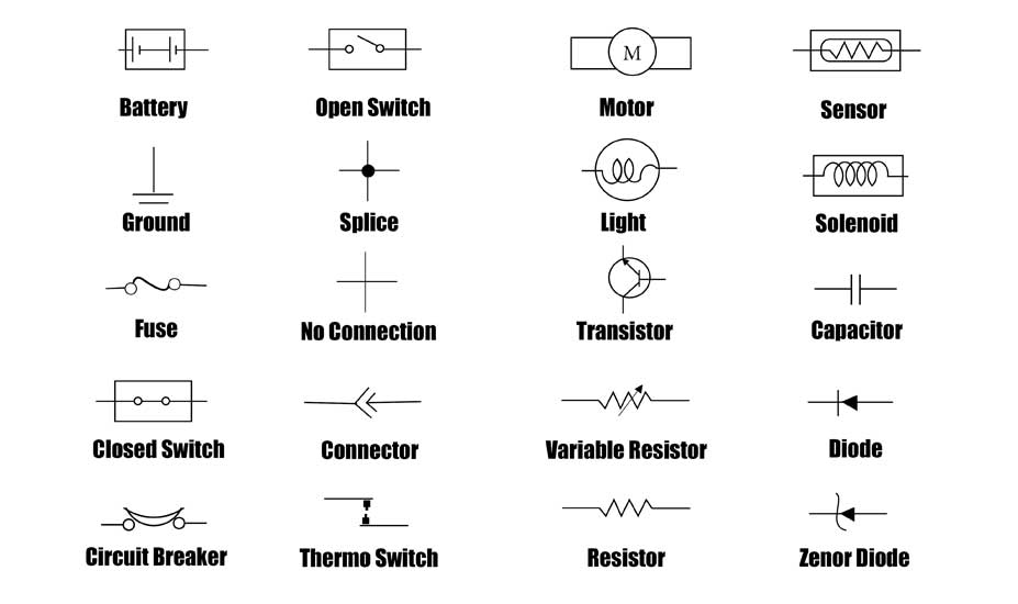
All automotive wires are color-coded to help you quickly and efficiently identify a specific wire in a wire harness or a connector. Colors often differ from one car manufacturer to another, but the code used to identify them in an automotive wiring diagram is always the same. The color will be noted using an abbreviation beside each wire. Car schematic electrical symbols identify both components and how a system operates. We use automotive schematics as a road map to fix cars in a timely manor. As you read through this page you can refer to the images as an example of basic automotive circuits. The pictures are labeled for your convenience.

Automotive Wiring Diagram Symbols Pdf Filestream Troy Wiring
Above are different electrical symbols used in automotive diagrams. The image in the question is the symbol for a variable resistor. (NTC) negative temperature coefficient sensors are variable resistors used as inputs for the engine, transmission, and air conditioning control modules. There are many electrical diagrams found in ASE tests. NTC. Electrical Symbols Chart. Before we begin please let me tell you what a wiring diagram won't do. Automotive wire diagrams don't show the actual position of parts or the physical appearance of the components.. You learn about the tools and the proper equipment required for automotive electrical tasks, but more importantly how to decipher.
