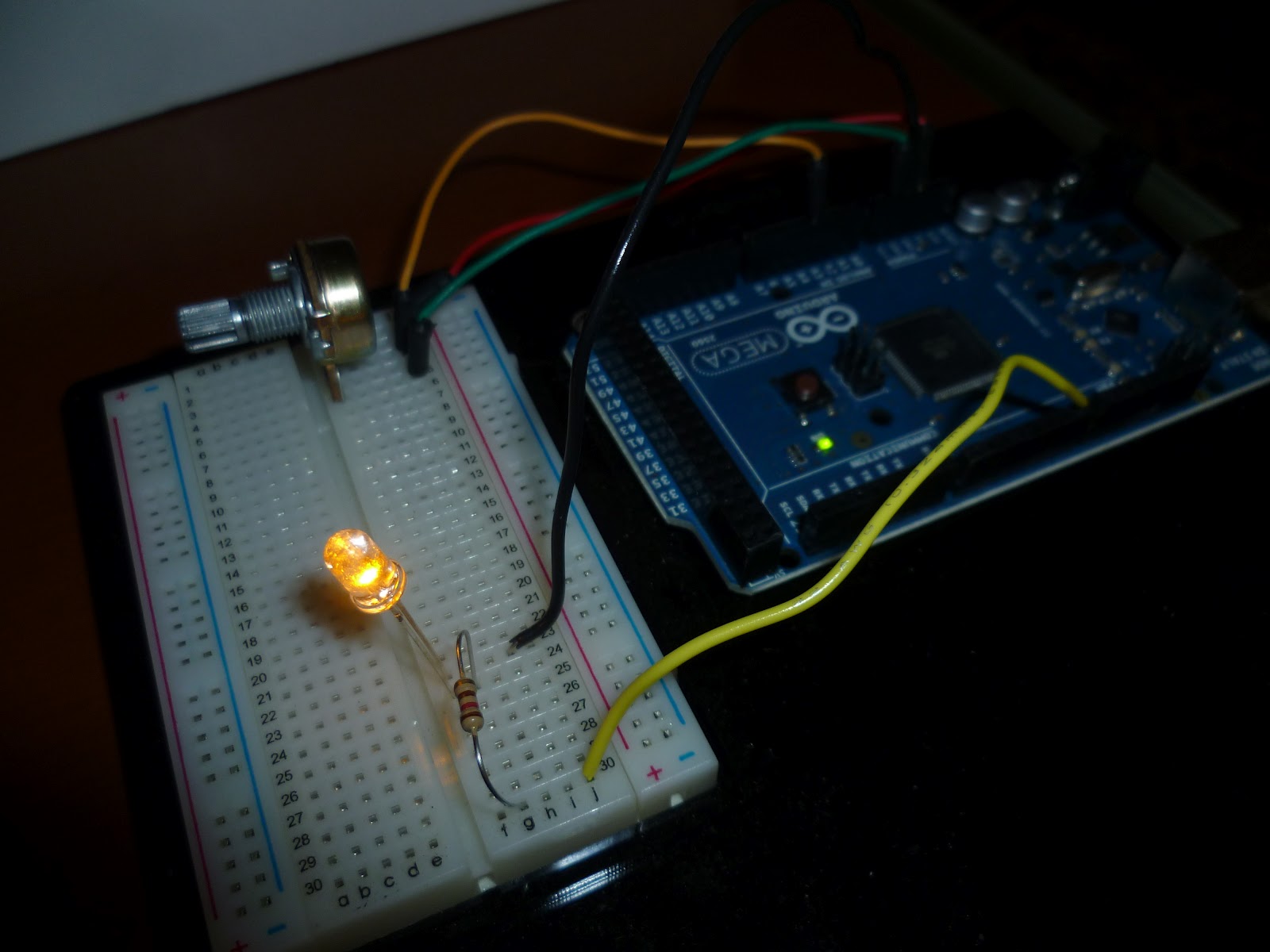
The brightness of an LED depends on the current through it. A resistor in series with the LED sets the current. In the circuit below, you can see the basic setup for controlling an LED: A potentiometer is a variable resistor that you can use to change the brightness of the LED. Just add the potentiometer in series with the LED. The PWM can be used to adjust the brightness of the LED by repeatedly switching between HIGH and LOW states. In this article, we will learn how to use the PWM to adjust the brightness of the LED. We will also learn how to write a program that uses the PWM output to gradually light up the LED. Brightness cannot be digitally adjusted

Arduino Display the LED Brightness on a LCD 16x2 Random Nerd Tutorials
LED brightness control is an essential aspect of lighting design, allowing us to adjust the intensity of light emitted by LEDs. The brightness of an LED bulb is determined by various factors, including the current flowing through it and the voltage applied to it. A common brightness-control circuit for LEDs uses an electrically controlled potentiometer (EPOT) to achieve digital control of the LED brightness. There is an alternative that reduces the number of ICs and control lines. You can control each LED driver directly with a single output port. Brightness can be set automatically from an external control voltage, or manually using a potentiometer. A safety thermistor on the LED shuts off the output should the LED overheat. The visible brightness of an LED display can be continuously varied by applying a pulsed-signal and varying its duty cycle. Usually, almost all 7-segment decoder ICs have a blanking input (RBI) connection to imply this type of brightness control. Because, the frequency in picture is above 50 Hz, unwanted flickering effect will not be noticeable.

Controlling a LED Brightness Circuit Crush
Note that we are connecting to the wiper and one end, not to both ends. Also, we have a 100 ohm resistor between the potentiometer and the LED. Please try to build this circuit, verify that the LED dims and brightens when the potentiometer is turned. The 100 ohms gets added to the resistance of the potentiometer! We'll start by adjusting the brightness of a single LED with a pulse-width modulated wave. Schematic of an LED connected to the square wave output of the PWM circuit. Connect a 180 ohm resistor and an LED of any color to pin 4 of the 74AC14 chip, as shown in the schematic. Turning the potentiometer dial changes the amount of "on time" the. The simplest way to operate an LED is to apply a voltage source across it with a resistor in series. The LED emits constant-intensity light as long as the operating voltage (V B) remains constant (although the intensity decreases with increasing ambient temperature). You can vary the light intensity as required by changing the resistor value. Step 1: Putting Potentiometer in Place -Take the red and black wire from the battery connector and put them on the side rails. -Attach a wire to each lead from the potentiometer and place on breadboard -Put the LED somewhere on the breadboard Step 2: Putting Resistors in Place

Push button led brightness control circuit YouTube
In this tutorial, we will learn how to control the brightness of an LED with two buttons using an Arduino. The circuit includes two buttons - one for increasing the brightness and the other for decreasing the brightness of the LED. By pressing the appropriate button, we can adjust the brightness of the LED. Considering the LED, we might be required to control its brightness, rather than simply switch it off or on. Using PWM, a pin is selected and its voltage is switched between 5v & 0v extremely fast, with the pin staying on each voltage for a variable amount of time. This gives the effect of a voltage between 5 and 0 being present.
Breadboard. LED - any color. 220 Ohm resistor. Potentiometer. A bunch of wires (male to female). Here is the circuit. You are learning how to use Arduino to build your own projects? Check out Arduino For Beginners and learn step by step. Steps to build the circuit: As a best practice we'll start with the ground (GND). The PWM technique mainly used to control the brightness of the LED, speed of DC motor, controlling a servo motor, or in other cases, where have to generate an analog signal using a digital source. We explained the PWM in detail in the previous article.

How to Make LED Brightness Controller Circuit Simple LED Brightness
This brightness-control circuit lets you adjust the LED brightness manually, using the UP and DOWN buttons. U2 is a current regulator (MAX16800) designed to drive a chain of LEDs with current as high as 200mA. In a standard application circuit, U2's internal regulator senses the drop across current-sense resistor R SENSE, in series with the LED. Led Brightness Control Circuit This project, a led brightness control circuit from 1976, shows how to control the brightness level of an LED display using only a very few components. Also the circuit does not require the use of a PWM module. This simple design allows you to easily control the brightness of any LED display.


