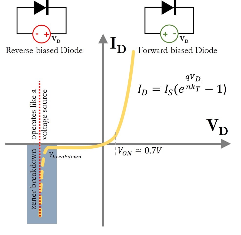
In electronics, diode modelling refers to the mathematical models used to approximate the actual behaviour of real diodes to enable calculations and circuit analysis. A diode 's I - V curve is nonlinear. Because the diode is a passive device, the I-V curve for a diode is obtained by a linear voltage sweep and is shown in Figure 1. When the applied voltage across the diode is greater than zero, i.e., V D > 0 V D > 0, the diode is said to be forward-biased.
Understanding CurrentVoltage Curves of Devices Technical Articles
The I-V Characteristic Curves, which is short for Current-Voltage Characteristic Curves or simply I-V curves of an electrical device or component, are a set of graphical curves which are used to define its operation within an electrical circuit. Thin lines are plots of experimental data, thick lines are two attempts to fit the diode equation. One curve is for n = 2 & Is = 10-10, the other curve is for n = 2 & Is = 10-9A. Include a copy of this plot in your write-up. List the final n and Is. Keep the gain of 10 op-amp circuit on your protoboard. The Shockley diode equation, or the diode law, named after transistor co-inventor William Shockley of Bell Labs, models the exponential current-voltage (I-V) relationship of semiconductor diodes in moderate constant current forward bias or reverse bias : where is the diode current, is the reverse-bias saturation current (or scale current), The current-voltage characteristics of four devices: a resistor with large resistance, a resistor with small resistance, a P-N junction diode, and a battery with nonzero internal resistance. The horizontal axis represents the voltage drop, the vertical axis the current.All four plots use the passive sign convention.. A current-voltage characteristic or I-V curve (current-voltage.

IV Curve Measurement How to Measure Solar Cell IV Curve Ossila
The curve reveals that a forward current (that is, current flowing from anode to cathode) of ~0 to ~ 45mA would flow through the diode when an external voltage of ~ 1.5V to ~ 2.0V is applied across the diode between anode and cathode. When we make a current-voltage plot (i-v curve) for an isolated resistor using Ohm's Law, the plot is straight line through the origin with a positive slope of 1/R. That's the i-v plot we get for a resistor all by itself. For the circuit in this video, the resistor is one of three components, connected between the diode and the voltage source. A diode is something that conducts current in one direction, and does not conduct current in the other direction. And the symbol we use for a diode looks like this. It has this big arrow here, that points in the direction of the forward current. One way to understand how a diode works is to draw an IV curve for it. The ideal diode i-v characteristic curve is shown below: Figure \(\PageIndex{1}\): Ideal diode equation. The ideal diode equation is very useful as a formula for current as a function of voltage. However, at times the inverse relation may be more useful; if the ideal diode equation is inverted and solved for voltage as a function of current, we.
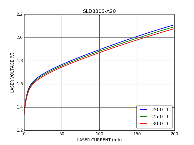
Laser IV characteristic curve measurement Koheron
Current Circuit: Diode I/V Curve This example shows the I/V curve of a diode. With a resistor, I (current) and V (voltage) are proportional (by Ohm's Law). With a diode, I and V have an exponential relationship. At the lower left, voltage is shown in green, and current in yellow. Abstract. Current versus voltage graphs, also known as I-V curves, are commonly used to characterize semiconductor devices. In diode datasheets, for example, manufacturers can measure these nonlinear devices and present it in graphical form to customers. These graphs also convey the device's AC resistance, which quantifies the current change.
Such an I-V curve can be extended on the left side of the graph, meaning with negative voltages applied on the device under test. Here, with the example of a diode, a reversed voltage means that the diode is reverse biased, and no current will circulate. The plot will stay close to the horizontal axis as I=0. An I-V curve (short for 'current-voltage characteristic curve'), is a graphical representation of the relationship between the voltage applied across an electrical device and the current flowing through it. It is one of the most common methods of determining how an electrical device functions in a circuit.

Silicon Diode IV Curve Electrical Academia
Diode Characteristic Curve. The characteristic curve of a junction diode is also called an I-V Curve. It is typically a graph showing the current flow at different forward voltages. The current is typically on the y-axis, and the voltage on the x-axis. This type of graph provides engineers with a visual record of the operating characteristics. The IV curve of a solar cell is the superposition of the IV curve of the solar cell diode in the dark with the light-generated current. 1 The light has the effect of shifting the IV curve down into the fourth quadrant where power can be extracted from the diode.
