In this video, we show you the best way to a pressure switch for 115V and 230V pumps. This method will work for any pump that runs directly off of a pressure. In this video, we show you the best. In this video, we review how pressure switches work in turning pumps on and off, and discuss how to wire a pressure switch. Please note that at 1:13, we say.

Definite Purpose Contactor Wiring Diagram Free Wiring Diagram
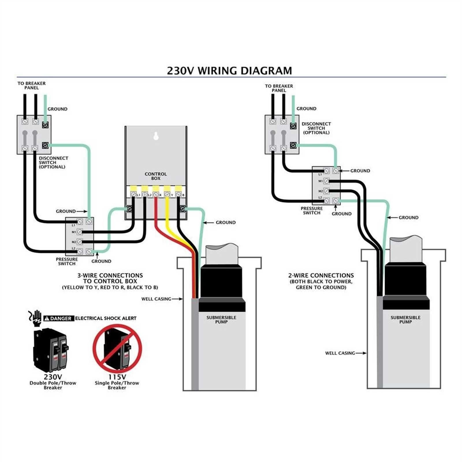
Attach the ground wire to the green ground screw. Attach the power supply from the main breaker to the outside terminals marked "Line" (L1/L2). Attach the ground wire to the green ground screw. Re-install the switch cover and reconnect the power. Test the pressure switch for several cycles to ensure that it is working properly. Step 3: Prepare the Wires. Measure and cut the appropriate length of wire for the installation. Strip about 1/2 inch of insulation from the ends of the wires using wire strippers. This will expose the copper conductor for connecting to the terminals of the pressure switch. For the most part 220V well pressure switches use a 2-wire submersible pump set up. Take A Picture of How It's Wired. An important part about wiring up a well pump pressure switch is knowing where the wires need to go. If you are replacing an old switch, an easy way to have a wiring diagram is to snap a picture using your phone BEFORE you. First, confirm you have power supply wires. Then, connect them with Line Terminals or "1 and 4" terminals. The wires are interchangeable. Connect the green ground wire coming from the power circuit to the ground screw fixed to the bottom of the box. Connect the motor wires to the Load Terminals or "2 and 3" terminals.

Unique Wiring Diagram for Air Compressor Pressure Switch Air
This is a short video on How To Wire A Pressure Switch on an electric air compressor. We give a brief explanation here on wiring two ver y common pressure sw. Read this guide to learn best practices and steps for wiring, testing, and replacing modern pressure switch designs. Use copper wire only Tightening torque 20 lb. in. (2.3 Nm). 1. KP pressure switches shall only be employed in the units/systems which comply with the requirements for charge limits and requirements for avoiding ignition sources of IEC 60335-2- 24:2012, IEC 60335-2-40:2018, IEC 60335-2-89:2019, ISO 5149, EN378-1:2016 or equivalent.. The "L" Series ASHCROFT snap action pressure switch has a NEMA-4 enclosure which is an epoxy coated aluminum casting. Two holes in the integral bracket are used to surface mount. wire directly to terminal blocks as required. Terminals are marked common (C), normally open (NO) and normally closed (NC). 4.12 (105) 2.25 (57) 2.50 (64) 0 .25.

Pressure Switch Wiring Diagram Printable Form, Templates and Letter
Step 1 - Cut off the Power. First and foremost, turn off the pump's main power supply. To do that, locate the circuit breaker that provides power to the pump and switch off the breaker. Make sure there are no live wires. After turning off the power, remember to check the wires with an electric tester. Using a single phase pressure switch wiring diagram has several advantages. First, it provides an easy-to-follow guide that is useful for both new installations and repairs. This makes it much easier to find out what each component does and how it connects to other components. Second, it allows for quick troubleshooting in the event of a fault.
Attach the ground wire to the green ground screw. Attach the power supply from the main breaker to the outside terminals marked "Line" (L1/L2). Attach the ground wire to the green ground screw. Re-install the switch cover and reconnect the power. Test the pressure switch for several cycles to ensure that it is working properly. To install a pressure switch for a well pump, first, turn off the power to the pump. Next, remove the old switch if present, and install the new one in its place. Connect the wires as per the pressure switch wiring diagram, ensuring that the connections are secure. Finally, adjust the pressure setting s as needed.

Wiring Diagram For Pressure Switch Well
Change the switch's front panel. Switch on the circuit's electricity again. Once the pressure switch has been wired, it may be attached to the pressure line by tightening the hex nut connection with a tool. Always use applied force to compress the male pipe firmly. Know more: 110 Volt Well Pump Wiring Diagram. Educational instructions for wiring a pressure switch for a submersible well pump application. Be sure to check out our website and blog at www.waterwellfaq..


